Surgical stapling device

a stapling device and surgical technology, applied in the direction of surgical staples, paper/cardboard containers, manufacturing tools, etc., can solve the problems of inability to release staples from anvils, device being trapped in-situ, staples being trapped within the device and attached to the tissue, etc., to achieve the effect of ensuring tissue penetration and facilitating ejection of staples

Inactive Publication Date: 2006-09-26
ABBOTT CARDIOVASCULAR
View PDF74 Cites 930 Cited by
  • Summary
  • Abstract
  • Description
  • Claims
  • Application Information

AI Technical Summary

Benefits of technology

[0011]The benefits of the invention over conventional stapling devices is that, firstly, as no anvil is required the staple can be advanced forward to a position where the staple back is in direct contact with the tissue being stapled. This is of particular advantage when the staple legs must remain short but the level of penetration into the tissue must be assured. Secondly, because there is no anvil component involved in the delivery mechanism, there is no requirement to add additional components so as to facilitate ejection of the staple over or around the anvil component or alternatively to move the anvil component to a position which allows the staple to advance forward and free up the device.

Problems solved by technology

There are a number of problems associated with the mechanism as described above.
Firstly, as the anvil is normally positioned in front of the staple it naturally becomes trapped between the back of the staple and the tissue into which it is being delivered causing the staple back to be spaced away from the tissue as opposed to lying tightly on its surface.
This is a particular problem in the field of vascular puncture closure when it is desirable to keep the legs of the staple as short as possible so as to avoid having the legs of the staple within the vessel lumen.
Secondly, the method of releasing the staple from the anvil can be both complicated and unreliable.
However, should the spring fail to operate or is prohibited from operating properly by virtue of some tissue blockage etc, the device will become trapped in-situ.
Again this generally involves very small metal components with relatively small movements which can fail to operate thereby leaving the staple trapped within the device and attached to the tissue into which it has been delivered.

Method used


Image

  • Surgical stapling device
  • Surgical stapling device
  • Surgical stapling device

Examples


Embodiment Construction

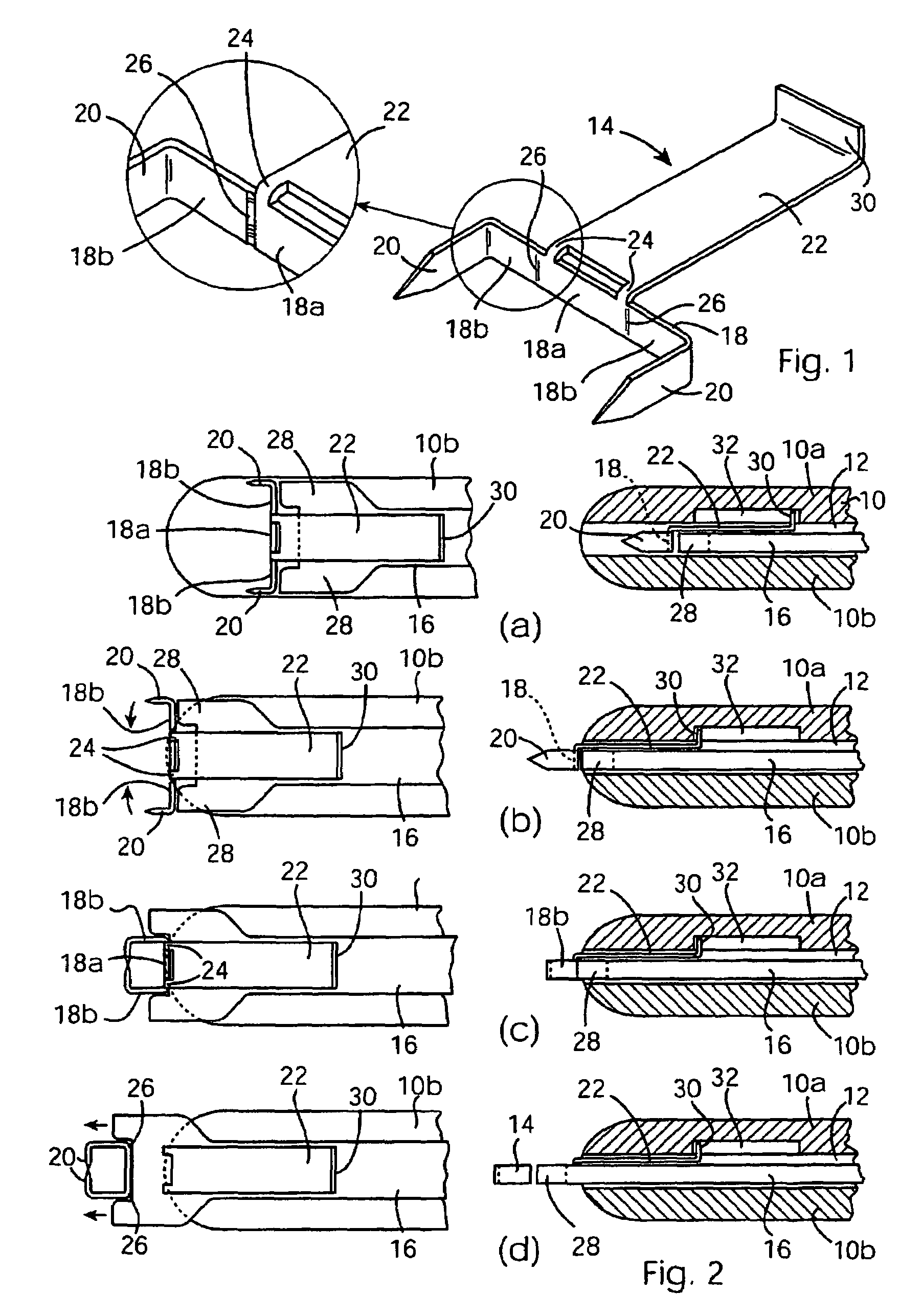
[0018]In the drawings the same reference numerals have been used for the same or equivalent parts.

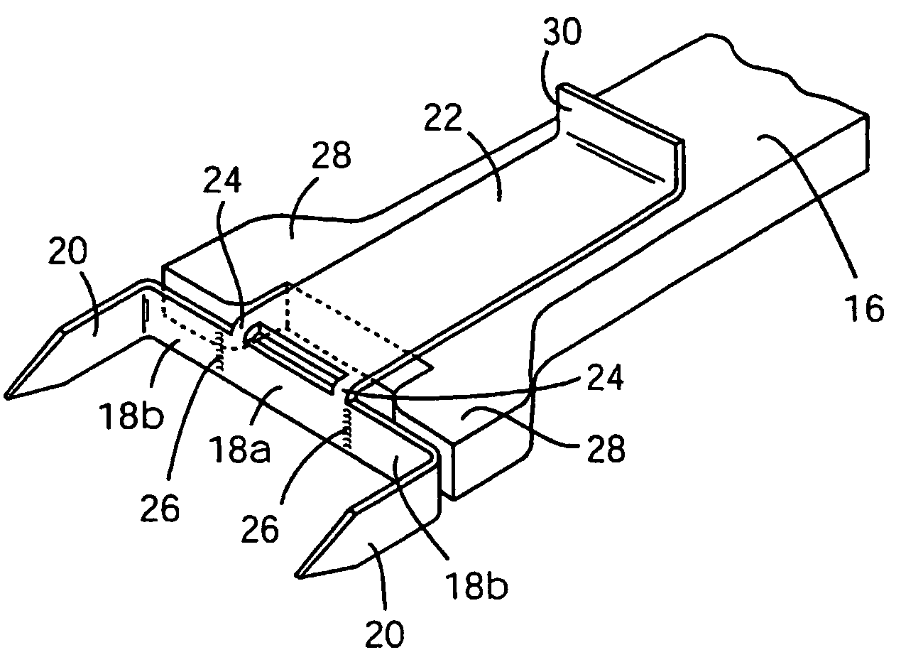
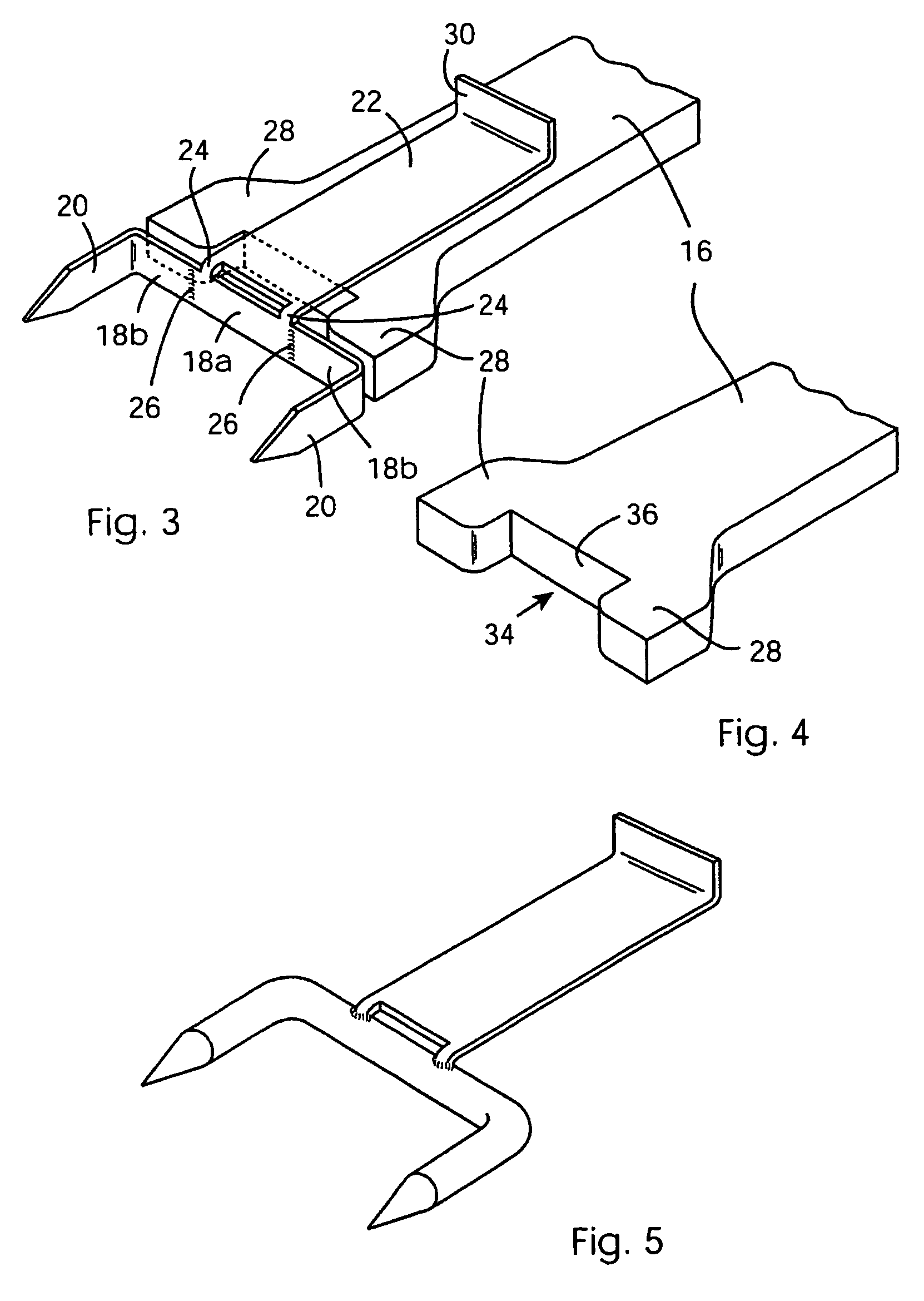
[0019]Referring to FIGS. 1 to 4, a surgical stapling device comprises an elongated housing or shaft 10 having upper and lower halves 10a and 10b defining between them a longitudinal channel 12 for slidably accommodating a staple 14 and a staple closing actuator 16 (in the plan views in the left hand column of FIG. 2 only the lower housing half 10b is shown). Only the free forward end of the housing 10 is shown in the drawings, since that is where the invention lies in the present embodiment. The rear end of the housing 10 is preferably formed with a pistol grip and the movement of the various components to be described may be effected by a trigger acting through a cam system. Such an arrangement is described in Irish Patent Application S2000 / 0722 which may be readily adapted to operate the device of the present embodiment.

[0020]The staple 14 is generally U-shaped, having a back 18 and t...


PUM

PropertyMeasurementUnit
Angleaaaaaaaaaa
Areaaaaaaaaaaa
Bending strengthaaaaaaaaaa

Abstract

A surgical stapler comprises an elongate housing 10 and a surgical staple 14 slidable longitudinally within the housing towards the free forward end thereof. The back 18 of the staple has a rearward extension 22. An actuator 16 is slidable forwardly within the housing for driving the staple towards the free end of the housing. An upstanding flange 30 on the extension 22 engages a stop 32 within the housing to restrain the back of the staple against forward movement of the actuator bends the staple to bring the free ends of the legs towards one another to close the staple. Further movement of the actuator then ruptures the join between the extension and the back of the staple to release the closed staple.

Description

FIELD OF THE INVENTION[0001]This invention relates to a surgical stapling device.BACKGROUND[0002]Surgical stapling devices have been in existence for many years. They are routinely used in surgical procedures mainly for the purposes of effecting a wound closure. Some of the most popular applications include closing a skin incision end-to-end or end-to-side anastomosis of internal (generally tubular) vessels such as the large bowel, etc. Current staplers are designed to deliver one or more staples in a serial fashion or a number of staples in one shot. Skin staplers, for example, deliver 30 or more staplers in a serial fashion. The staples are stacked within the device and during the firing operation one staple is advanced from the stack and delivered through the head of the device. During the following cycle another staple is advanced from the top of the stack and again delivered through the head of the device and so on. In one shot devices such as a bowel anastomosis stapler the st...

Claims


Application Information

Patent Timeline
IPC IPC(8): A61B17/068A61B17/064A61B17/10A61B17/08A61B19/00
CPCA61B17/0644A61B17/0684A61B2019/307A61B2017/0641A61B2090/037
Inventor CUMMINSHOOI, PAUL
Owner ABBOTT CARDIOVASCULAR
Why Eureka
Try Eureka