
Measurement and antenna placement tool for establishing a cell site

a cell site and measurement technology, applied in the field of cellular communication systems, can solve the problems of many problems, many problems associated with the modulation, data rate, or system protocols that go undiscovered, and achieve the effect of accurately predicting and evaluating the performance of the cellular system

Inactive Publication Date: 2006-09-19
AVAYA INC
View PDF19 Cites 22 Cited by
  • Summary
  • Abstract
  • Description
  • Claims
  • Application Information

AI Technical Summary

Benefits of technology

[0008]The present invention overcomes the problems associated with the prior art and provides an apparatus and system for accurately predicting and evaluating cellular system performance before an actual system infrastructure is installed at a site. In accordance with an embodiment of the invention, only two persons (or under certain conditions, as few as one) are required to operate the portable measurement and antenna placement (MAP) tools of the invention, and evaluate system performance (e.g., voice quality, RSSI, etc.) at a site without the system being in place. A user can measure out the size of cells using a bar graph display that shows the range of acceptable signal levels for the system, and an audible warning tone that signals the user when the cell edge has been exceeded. In addition, other quality determinative system parameters (e.g., bit error rate (BER), etc.) can be evaluated simultaneously with voice quality and average RSSI.

Problems solved by technology

While the above described method is reliable, the collection of the critical data is very tedious.
Moreover, problems often arise after the system has been installed due to sources of interference that were not considered or that did not exist during the information gathering (i.e., site examination) phase, or due to human error in measuring and / or estimating signal obstructions and / or material make-up.
As a result, many problems associated with the modulation, data rates, or protocols of systems go undiscovered until the full system infrastructure is installed at a site.
For example, holes (i.e., areas through which a signal is not being transmitted) in the coverage area due to e.g., incomplete surveys, can require costly additions or moves of system infrastructure.
The costs associated with correcting these types of problems on site can be enormous and prohibitive.

Method used


Image

  • Measurement and antenna placement tool for establishing a cell site
  • Measurement and antenna placement tool for establishing a cell site
  • Measurement and antenna placement tool for establishing a cell site

Examples


Embodiment Construction

[0022]A preferred embodiment of the present invention will now be described with reference to FIGS. 3–8. Other embodiments may be realized and structural, or logical changes may be made to the disclosed embodiment without departing from the spirit or scope of the present invention.

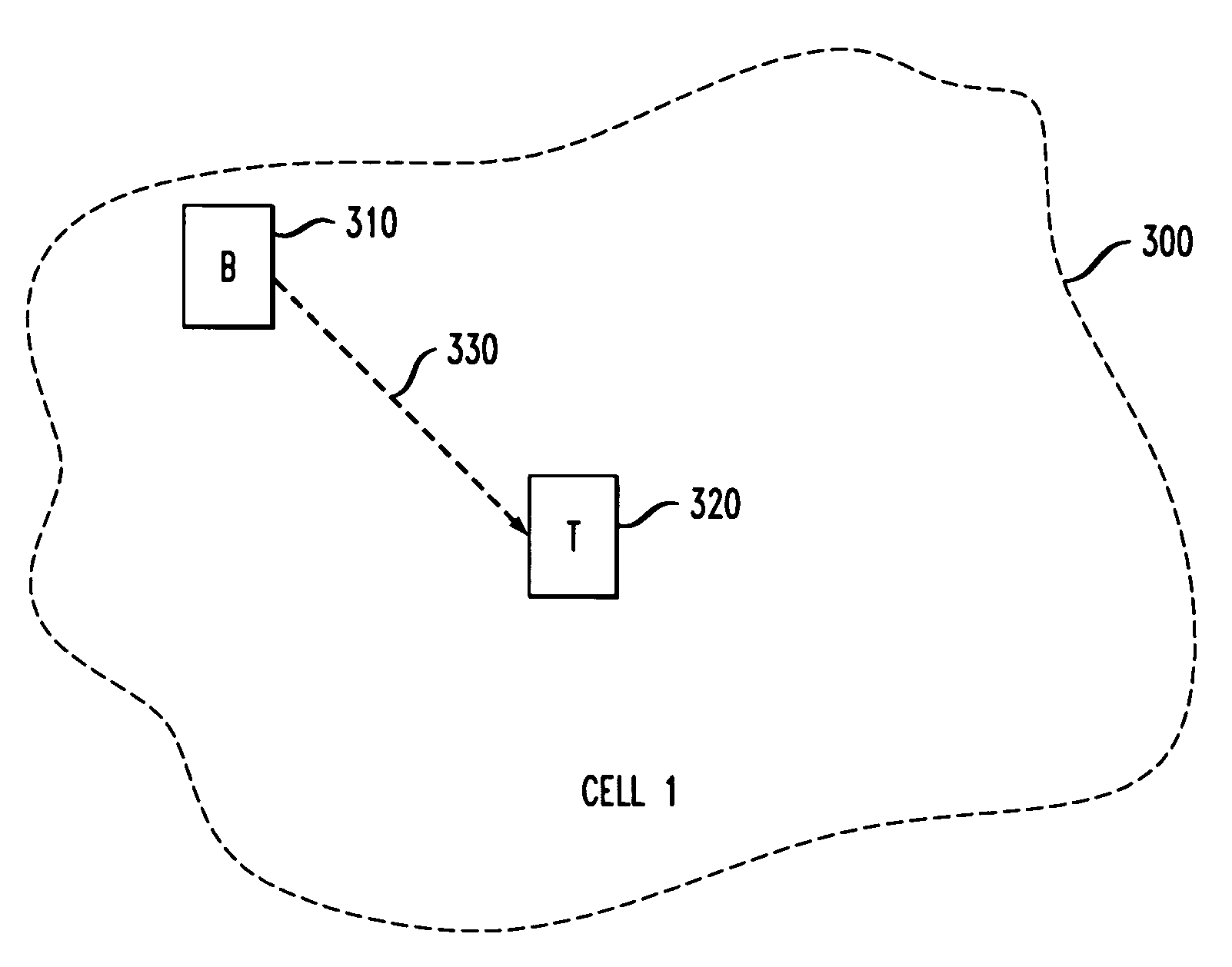
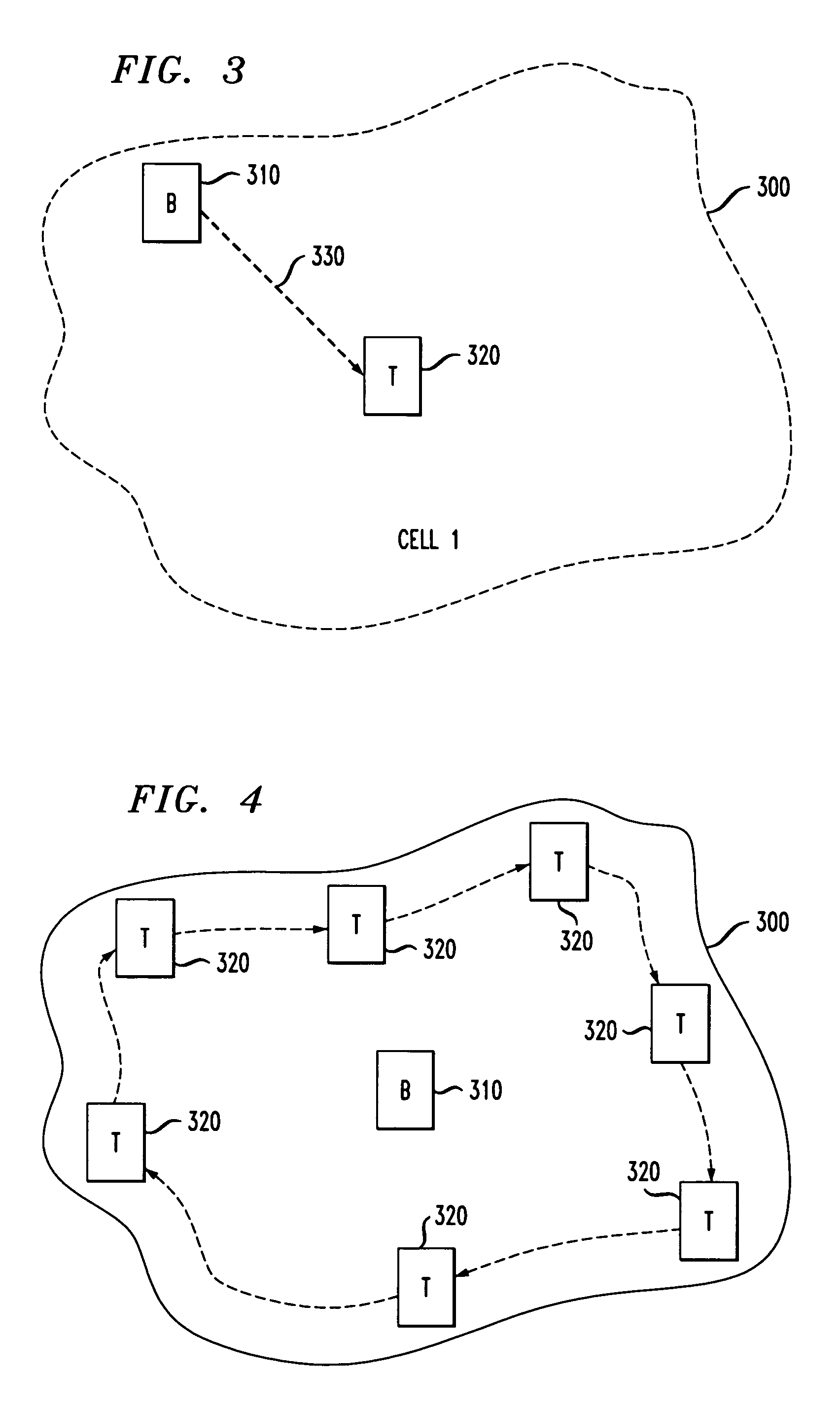
[0023]FIG. 3 depicts a cell 300 being formed in accordance with an embodiment of the invention. The measurement and antenna placement (MAP) tool device consists of two identical units; a base unit 310 and a terminal unit 320. That is, the MAP tools 310, 320 are intended to be used in pairs and are configured via firmware into a master / slave arrangement, whereby the base unit 310 acts as a master unit, providing a master timing reference signal and transmitting a test signal and the terminal unit 320 acts as a slave, aligning itself to the master timing and receiving the test signal and measuring the quality of the received test signal. It should be noted that either one of the identical units 310, 320 can ...


PUM


Abstract

The present invention provides an apparatus and system for accurately predicting and evaluating cellular system performance before an actual system is installed at a site. In accordance with an embodiment of the invention, only two persons (or under certain conditions, as few as one) are required to operate the portable measurement and antenna placement (MAP) tools of the invention, and evaluate system performance (e.g., voice quality) at varied locations of a site without the system being in place. A user can measure out the size of cells using a bar graph display that shows the range of acceptable signal levels for the system, and an audible warning tone that signals the user when the cell edge has been exceeded. In addition, other quality determinative system parameters (e.g., bit error rate (BER), etc.) can be evaluated simultaneously with voice quality and average received signal strength.

Description

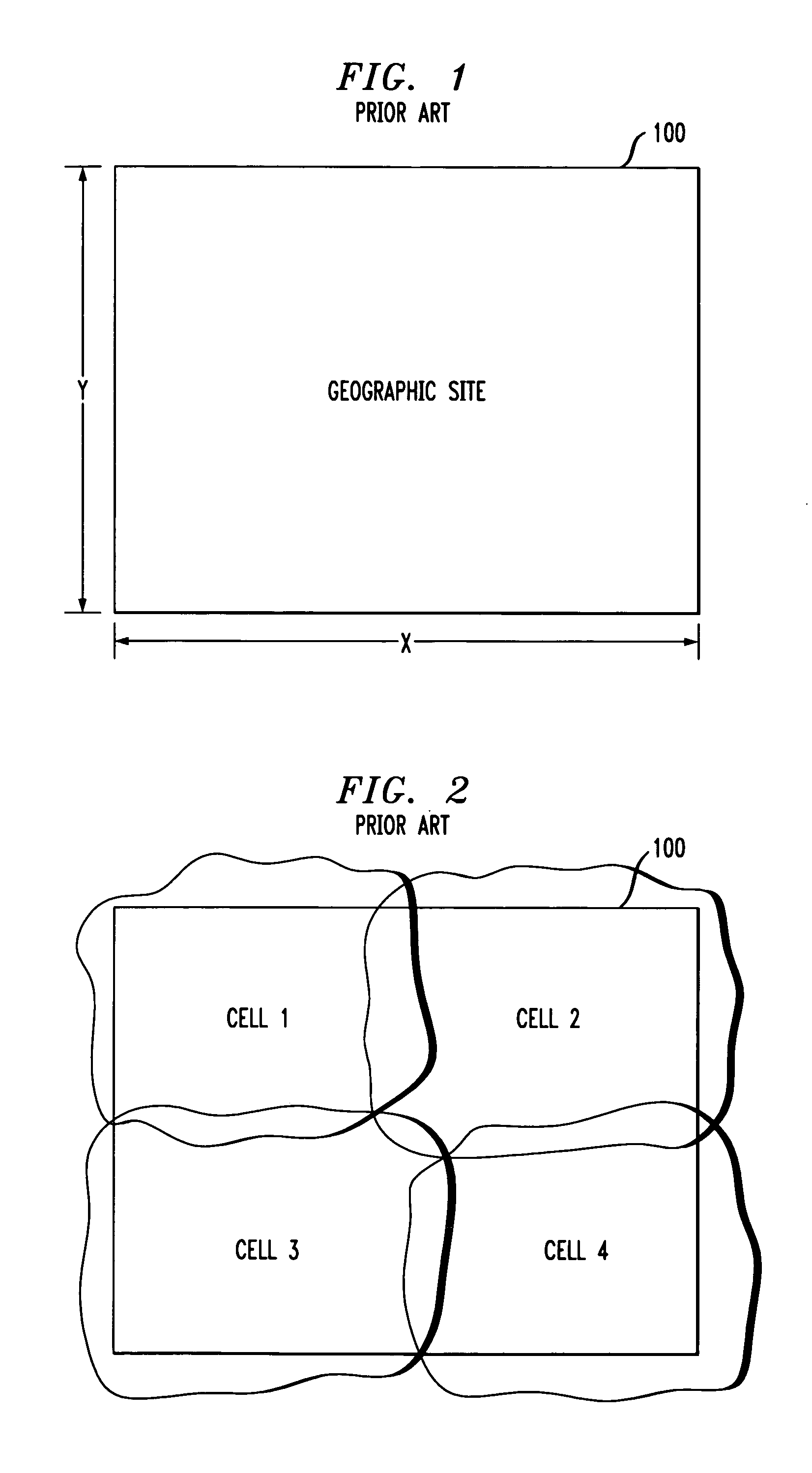
BACKGROUND OF THE INVENTION[0001]1. Field of the Invention[0002]The present invention relates to the field of cellular communication systems. More specifically, it relates to a device for establishing cells at a predetermined geographic site and for predicting the performance of the cells before an actual cellular system has been implemented at the site.[0003]2. Description of the Related Art[0004]A wireless, cellular telephone system is a large, complex communication network, characterized by multiple users roaming throughout an extensive coverage area while communicating with others within the same coverage area, or some other coverage area.[0005]FIG. 1, for example, illustrates a typical geographic site 100 intended to receive a wireless infrastructure (e.g., antennas, repeaters, etc.) and become part of the communications network. The geographic site 100 has a length X and a width Y, where X and Y may form an area of e.g., one square mile. Within geographic site 100, a plurality...

Claims


Application Information

Patent Timeline
Patent Type & Authority Patents(United States)
IPC IPC(8): H04Q7/20H04W16/18
CPCH04W16/18
Inventor BRIDGES, SYDNEY D.DESANTIS, CHARLES MICHAELKLEIN, JANENOSSEN, STEVE J.
Owner AVAYA INC
Learn More