
Endourethral device and method

a technology of endotracheal and endotracheal tube, which is applied in the field of endotracheal devices, can solve the problems that flow rate and pattern cannot be expected to normalize with an endotracheal tub

Inactive Publication Date: 2006-09-19
SRS MEDICAL SYST INC
View PDF101 Cites 78 Cited by
  • Summary
  • Abstract
  • Description
  • Claims
  • Application Information

AI Technical Summary

Benefits of technology

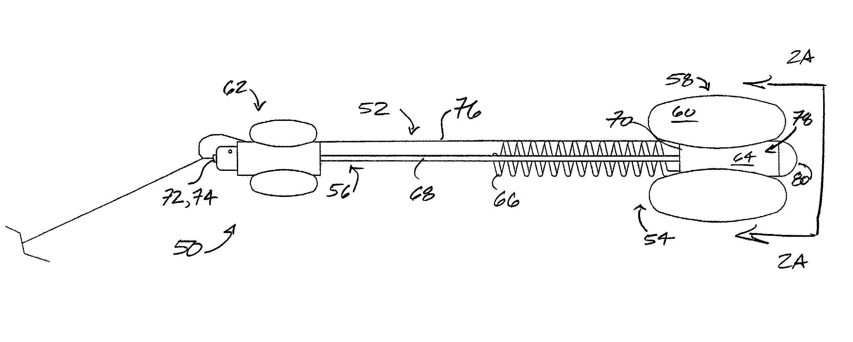
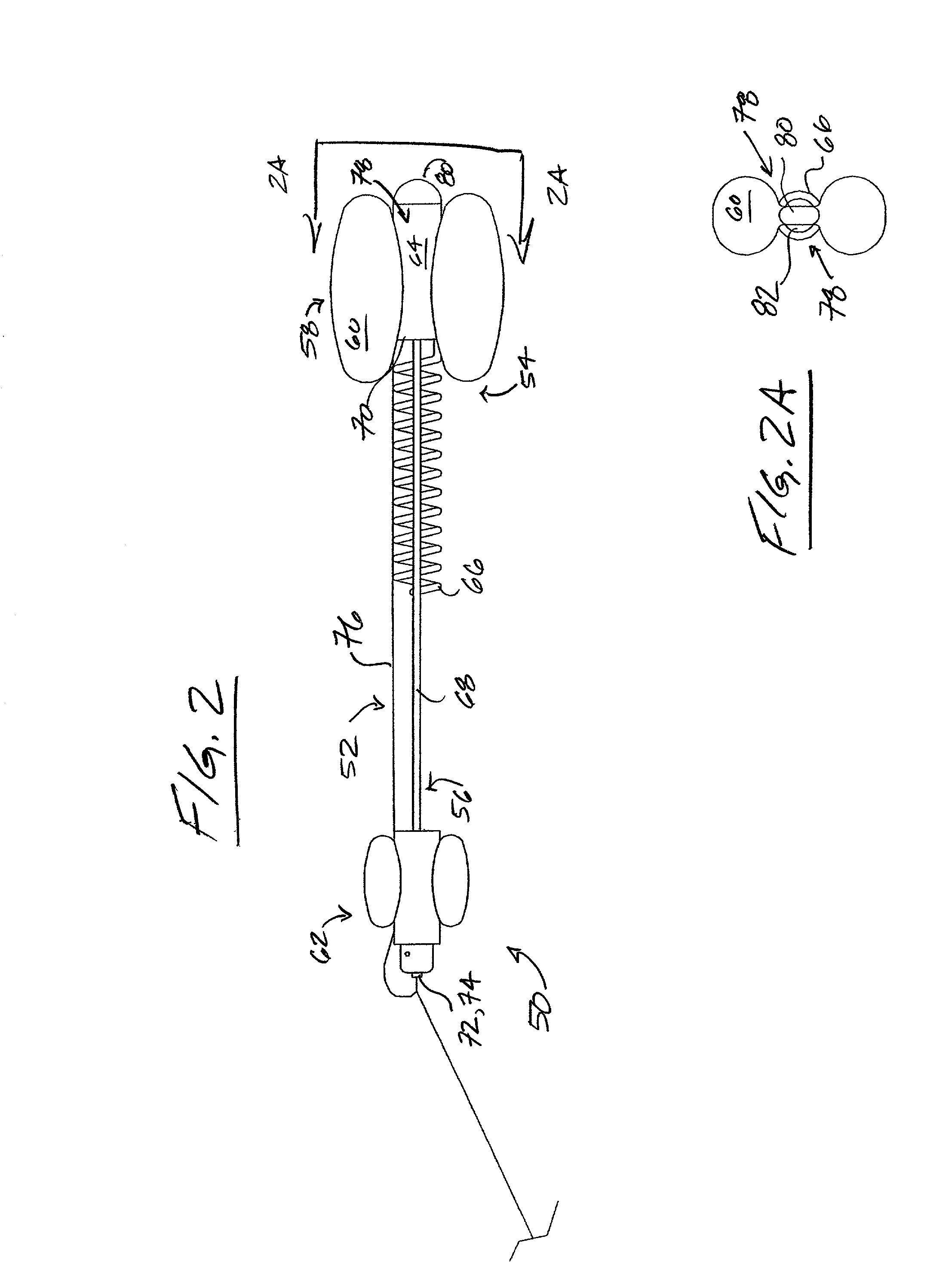
[0019]Preferably, the device is positioned to traverse the prostatic urethra from the bladder neck to the proximal side of the urinary sphincter, being held in position by a balloon on its proximal end, and a soft silicone anchor on the distal end. Similar to a Foley-type catheter, the 5 cc balloon on the proximal tip is positioned in the bladder neck to provide retention of the endourethral device. The silicone anchor is attached to the distal end of the endourethral device by means of a suture. The length of the suture is such that it traverses the length of the sphincter, positioning the anchor on the distal side of the sphincter to prevent migration inward to the bladder. Once positioned, the endourethral device conducts urine flow across the prostatic urethra during the physiologic functioning of bladder contraction and sphincter relaxation, removing the influence of potential prostatic urethral obstruction on voiding function. By providing a fixed orifice through the desired segment of the prostatic urethra during standard uroflow testing and at home monitoring, the endourethral device permits information acquisition about bladder function not currently obtainable with heretofore known structures and / or methodologies.

Problems solved by technology

Conversely, if decreased flow is primarily related to dysfunction of the bladder, or a combination of bladder dysfunction and obstruction, the flow rate and pattern would not be expected to normalize with a endourethral device in place.

Method used


Image

  • Endourethral device  and method
  • Endourethral device  and method
  • Endourethral device  and method

Examples


Embodiment Construction

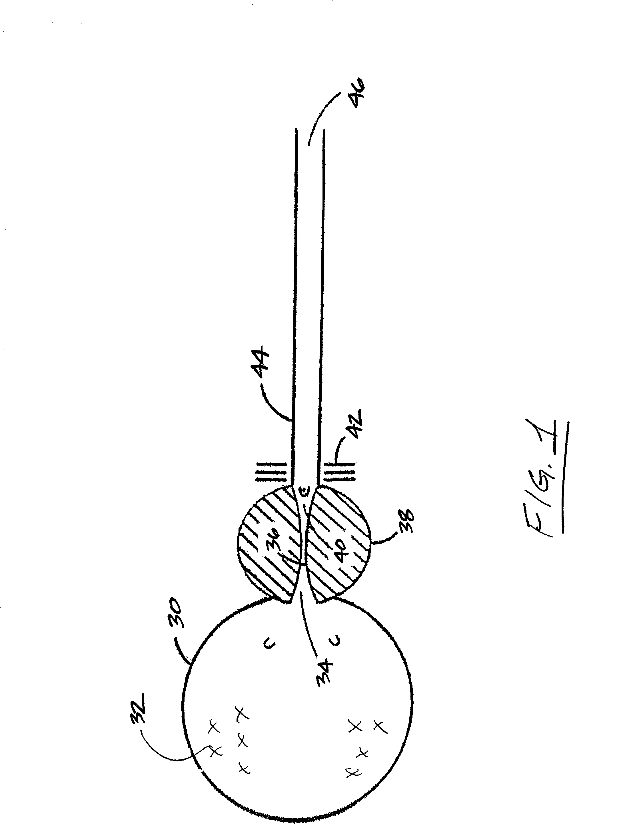
[0036]A schematic of the human male urinary bladder and urinary passage (i.e., the lower urinary tract) is presented in FIG. 1. The bladder 30 temporarily stores urine 32 and periodically expels it when the bladder neck 34 opens, as the bladder 30 contracts. Urine 32 passes through the prostatic urethra 36, which is completely surrounded by the prostate 38. The distal limit of prostate 38 is marked by a small projection called the verumontanum 40. This is a important landmark because distal thereto, is the external urethral sphincter 42, which relaxes soon after the urination process begins. Beyond this is the urethra 44, affording a free passage of urine 32 external to body, beyond the external urethral meatus 46.

[0037]Generally referencing FIG. 2 (see also FIGS. 8, 10&12 having reference numerals +600, +700, and +800 respectively for like structures), there is shown an endourethral device 50 which generally comprises an elongate member 52 having proximal 54 and distal 56 segments,...


PUM


Abstract

An endourethral device is provided having an elongate member having proximal and distal segments, the elongate member positionable within a lower urinary tract so as to at least partially traverses a prostatic urethra. A proximal anchor, adapted to abuttingly engage portions of a bladder neck so as to at least proximally anchor the device, is supported at least indirectly by the proximal segment of said elongate member. The proximal anchor includes bladder engaging elements radially extending from the proximal segment of said elongate member, urine being freely dischargable about at least the proximal segment so as to substantially bathe the bladder neck therewith.

Description

[0001]This is a regular application filed under 35 U.S.C. §111(a) claiming priority under 35 U.S.C. 119(e) (1), of provisional application Ser. No. 60 / 263,202, having a filing date of Jan. 23, 2001; provisional application Ser. No. 60 / 295,535, having a filing date of Jun. 4, 2001; and, provisional application Ser. No. 60 / 329,859, having a filing date of Oct. 18, 2001, all of which were filed pursuant to 35 U.S.C. §111(b).TECHNICAL FIELD[0002]The present invention generally relates to medical devices, more particularly to endourethral devices, and still more particularly to endourethral devices having anchor structures which permit the discharge of urine therethrough and / or there around.BACKGROUND OF THE INVENTION[0003]Urinary problems can have serious consequences, particularly when the problem is one of retention, incomplete emptying, or dysuria. Urine flow problems include urine retention, incontinence, and difficult urination. Retention can result from any of a number of causes, ...

Claims


Application Information

Patent Timeline
Patent Type & Authority Patents(United States)
IPC IPC(8): A61F2/00A61M25/00A61M1/00
CPCA61M25/0017F21W2121/006A61M2210/1089A61M2210/1085Y10S128/25
Inventor WHALEN, MARK J.WILLARD, LLOYD K.REID, JOHN M.
Owner SRS MEDICAL SYST INC
Learn More