
Condensate removal system and method for facilitating cooling of an electronics system

a technology of condensate removal and electronics, which is applied in the direction of electrical apparatus casings/cabinets/drawers, heating types, domestic cooling apparatus, etc., and can solve problems such as recirculation problems, unmanageable approach at the frame level, and excessive sensible heat load carried by the air exiting the fram

Active Publication Date: 2006-09-12
INT BUSINESS MASCH CORP
View PDF9 Cites 64 Cited by
  • Summary
  • Abstract
  • Description
  • Claims
  • Application Information

AI Technical Summary

Problems solved by technology

This trend poses a cooing challenge at both the module and system level.
However, this approach is becoming unmanageable at the frame level in the context of a computer installation (e.g., data center).
The sensible heat load carried by the air exiting the frame will eventually exceed the ability of the room air conditioning to effectively handle the load.
In such installations not only will the room air conditioning be challenged, but the situation may also result in recirculation problems with some fraction of the “hot” air exiting one frame being sucked into the air inlets of a nearby frame.
Furthermore, while the acoustic noise level of a powerful (or higher RPM) air moving device in a single drawer may be within acceptable acoustic limits, because of the number of air moving devices in the frame, the total acoustic noise at the frame level may not be acceptable.
In addition, the openings required in the frame for the entry and exit of airflow makes it difficult, if not impossible to provide effective acoustic treatment to reduce the acoustic noise level outside the frame.
Finally, as operating frequencies continue to increase, we are approaching the point where electromagnetic (EMC) cross talk between tightly spaced computer frames is becoming a problem largely due to the presence of the openings in the covers required for airflow.

Method used


Image

  • Condensate removal system and method for facilitating cooling of an electronics system
  • Condensate removal system and method for facilitating cooling of an electronics system
  • Condensate removal system and method for facilitating cooling of an electronics system

Examples


Embodiment Construction

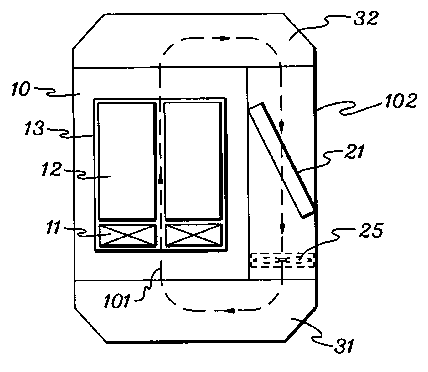
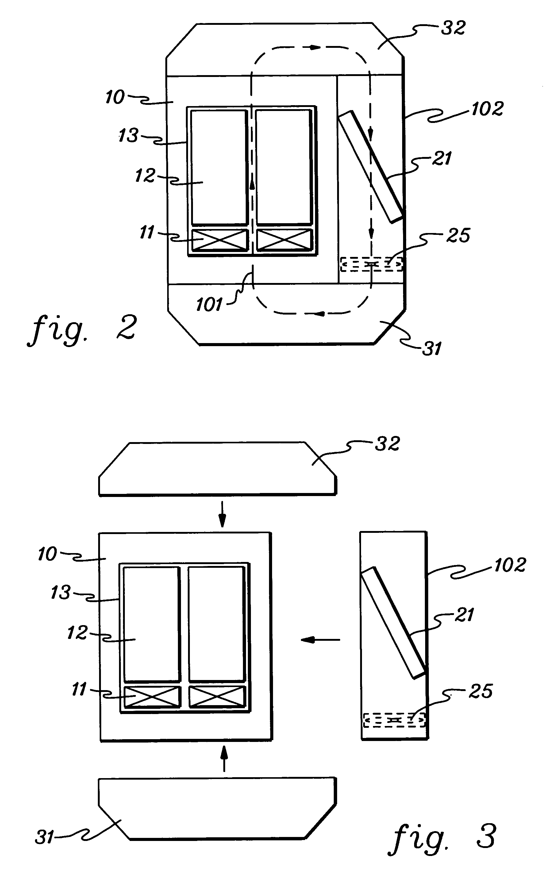
[0023]As used herein “electronics system” comprises any housing, frame, rack, compartment, etc., containing one or more heat generating components of a computer system or other electronics unit requiring cooling. The term “electronics rack” includes any frame or rack having a heat generating component of a computer system or electronics system and may be for example, a stand alone computer processor having high, mid or low end processing capability. In one embodiment, an electronics rack may comprise multiple electronics drawers each having one or more heat generating components disposed therein requiring cooling.

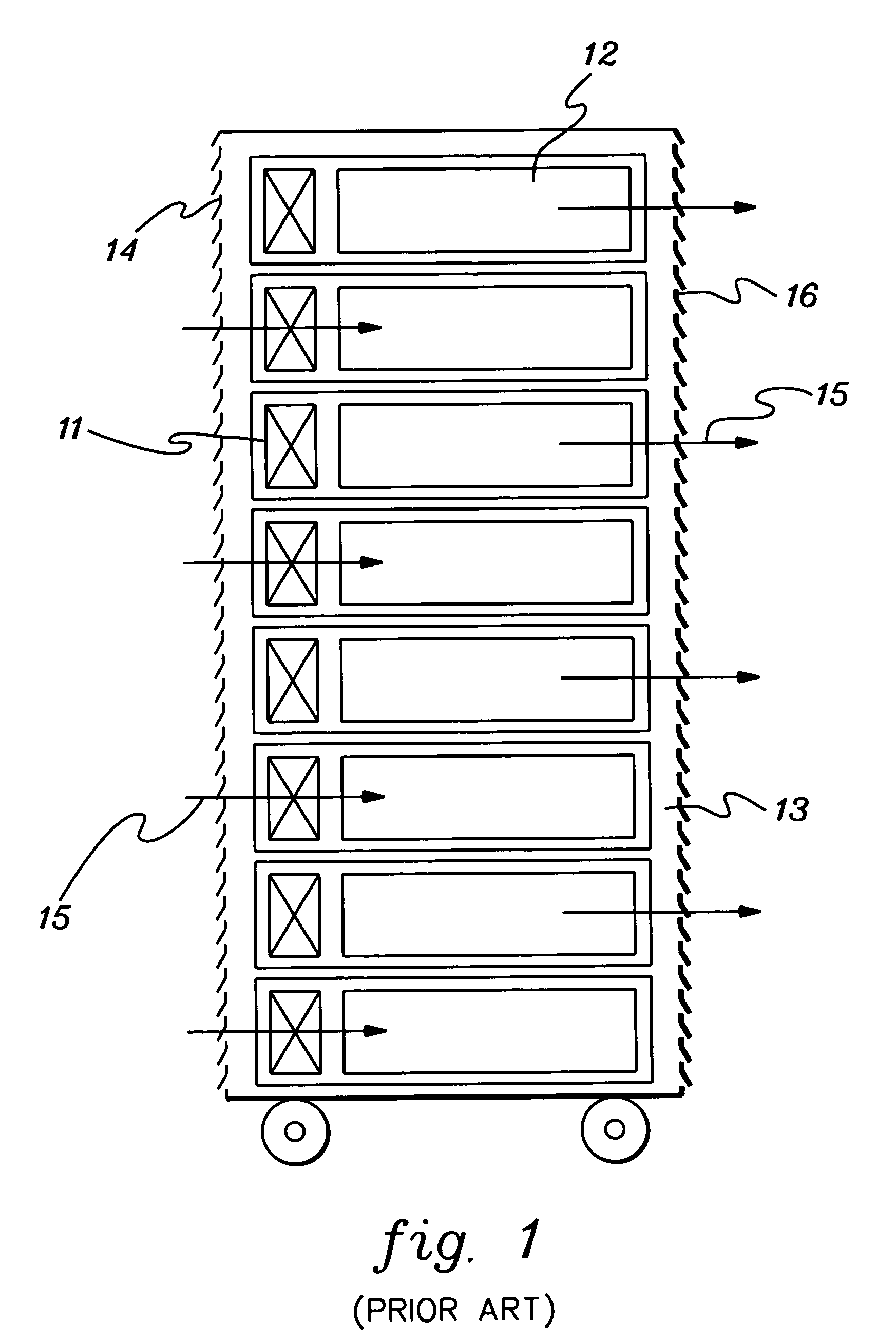
[0024]As shown in FIG. 1, in rack-mounted configurations typical in the prior art, a plurality of air moving devices (e.g. fan or blower 11) provides the forced airflow 15 needed to cool the electronic components 12 within the drawer 13. Cool air is taken in through the louvered covers 14 in the front of the frame and exhausted out of the louvered covers 16 in the back of t...


PUM


Abstract

System and method are provided for removing condensate from an air-to-liquid heat exchanger of a combined air / liquid enclosed apparatus for cooling rack-mounted electronic equipment. The condensate removal system includes a condensate collector for collecting liquid condensate from the air-to-liquid heat exchanger, and a vaporizing chamber in fluid communication with the condensate collector for receiving collected liquid therefrom. An actively controlled vaporizer vaporizes collected liquid within the vaporizing chamber and a vapor exhaust is in communication with the vaporizing chamber for venting vapor from the vaporizing chamber outside the cabinet containing the combined air / liquid cooling apparatus and rack-mounted electronic equipment.

Description

CROSS REFERENCE TO RELATED APPLICATIONS[0001]This application contains subject matter which is related to the subject matter of the following applications, each of which is assigned to the same assignee as this application and each of which is hereby incorporated herein by reference in its entirety:[0002]“Method and Apparatus For Combined Air and Liquid Cooling Of Stacked Electronics Components”, Chu et al., Ser. No. 10 / 303,284, filed Nov. 25, 2002; and[0003]“Method and System For Cooling Electronics Racks Using Pre-Cooled Air”, Chu et al., Ser. No. 10 / 612,355, filed Jul. 2, 2003.TECHNICAL FIELD[0004]The present invention relates in general to cooling assemblies and other apparatus used for removing heat from electronic devices, modules and systems. More particularly, this invention relates to systems and methods for removing condensate from an electronics cooling system, wherein the electronics cooling system could comprise an air-to-liquid heat exchanger disposed within the cabine...

Claims


Application Information

Patent Timeline
Patent Type & Authority Patents(United States)
IPC IPC(8): F25D23/12F24F13/22F25D21/00F25D21/14F25J3/00H05K5/02H05K7/20
CPCF24F13/222H05K7/20609H05K5/0213H05K7/20736H05K5/0212
Inventor CHU, RICHARD C.ELLSWORTH, JR., MICHAEL J.SCHMIDT, ROGER R.SIMONS, ROBERT E.
Owner INT BUSINESS MASCH CORP
Learn More