Disc apparatus and servo pattern write method thereof

a technology of servo pattern and write head, which is applied in the direction of maintaining head carrier alignment, digital recording, instruments, etc., can solve the problems of increased time and labor, affecting the accuracy the method of writing the auxiliary burst signal is also thought to have a drawback in view of write efficiency, so as to improve the positioning precision of the write head, improve the positioning precision of the recording element, and ensure the positioning precision of the read head. constant

Inactive Publication Date: 2006-09-05
KK TOSHIBA
View PDF21 Cites 8 Cited by
  • Summary
  • Abstract
  • Description
  • Claims
  • Application Information

AI Technical Summary

Benefits of technology

[0011]The present invention was made in view of the above-described circumstances, and an object thereof is to provide a disc apparatus having a disc with servo information written thereon and a method of writing servo patterns on the disc, and more particularly, to a disc apparatus having a self-servowrite capability that realizes improvement in positioning precision of a write head by constantly ensuring positioning precision of a read head and a servo pattern write method thereof.
[0014]Such two servo patterns prewritten on the disc indicate that, in additional write of the second servo pattern based on the read of the first servo pattern and additional write of the first servo pattern based on the read of the second servo pattern, it was possible to prevent the positioning of “the read element” (read head) based on an output thereof from being performed near a dynamic range saturation point of a position error signal output. Therefore, such two prewritten servo patterns can be considered as a trace indicating that it was possible to improve positioning precision of “the recording element” (write head) corresponding the situation that the radial direction interval between “the read element” and “the recording element” (read / write heads) changes depending on the radial direction position.
[0017]This servo pattern write method is one of the methods used for providing the above-described disc apparatus. Here, in the second and fourth steps, it is detected that the offset of the position of the read head added at the read of the servo pattern has reached approximately one eighth of the track width, and thereafter, the subsequent step continues. With the offset corresponding to approximately one eighth of the track width, it is possible to avoid that the positioning is performed near the dynamic range saturation point of the position error signal output. Therefore, according to this method, positioning precision of the read head is constantly ensured, which can improve positioning precision of the write head. Incidentally, the expression “on an outer side / inner side in the radial direction” is used in order to imply that the additional write for the servo write may progress in an outward direction from the inner side of the disc or may progress in an inward direction from the outer side of the disc.
[0018]According to the present invention, in self-servowrite, positioning precision of “the read element” (read head) is constantly ensured, so that it is possible to improve positioning precision of “the recording element” (write head).

Problems solved by technology

The methods disclosed in Patent documents 1, 2 are thought to have a drawback in view of positioning precision of the read head since it is sometimes unavoidable to detect the position error signal near a dynamic range saturation point of the output thereof at the time of the positioning of the read head.
The method of writing the auxiliary burst signal is also thought to have a drawback in view of write efficiency because it requires an increased time and labor.
Further, Patent document 3 does not teach in its disclosed contents what measure should be taken to solve the situation that the radial direction interval between the read / write heads changes depending on the radial direction position.

Method used


Image

  • Disc apparatus and servo pattern write method thereof
  • Disc apparatus and servo pattern write method thereof
  • Disc apparatus and servo pattern write method thereof

Examples


embodiment

Explanation of Embodiment

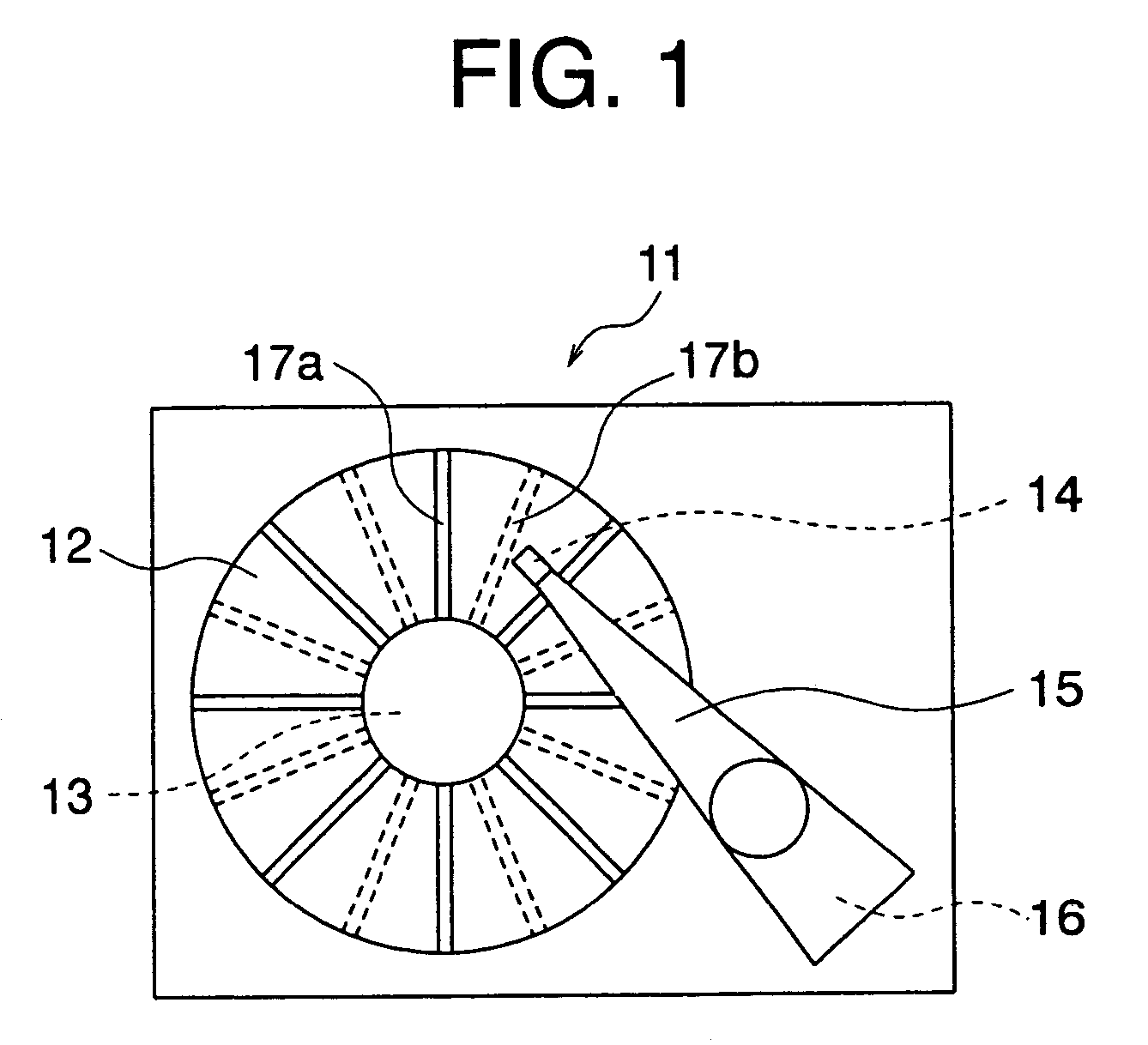
[0032]Embodiments of the present invention will be described with reference to the drawings, but these drawings are provided only for an illustrative purpose and by no means are intended to limit the present invention.

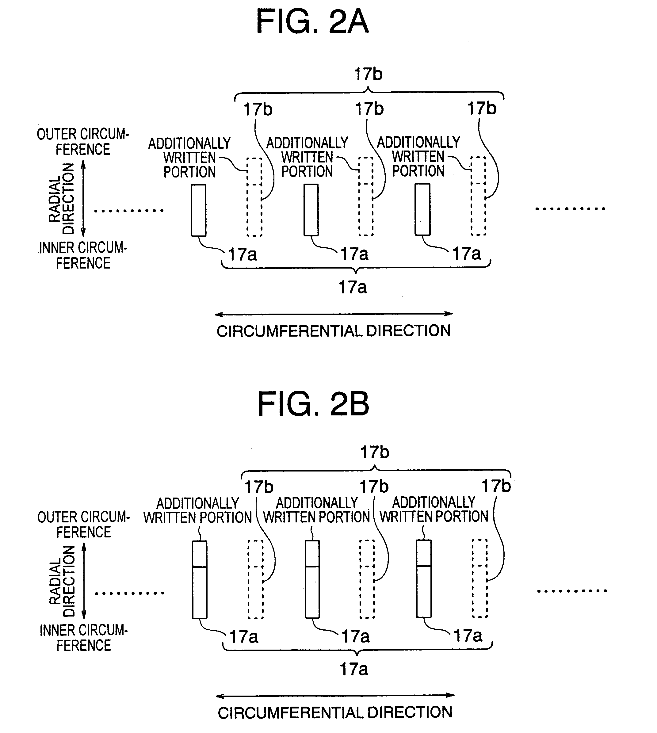
[0033]As a mode of an embodiment of the disc apparatus of the present invention, a width of each track defined by the burst pattern can be substantially constant, not dependent on a radial direction position thereof on the disc. This is the result of the arrangement of the tracks with the highest compactness.

[0034]As another mode, the burst patterns may be four kinds of burst patterns whose positions in a circumferential direction are different. The four kinds of burst patterns whose positions in the circumferential direction are different are often used as a servo pattern of a magnetic disc apparatus.

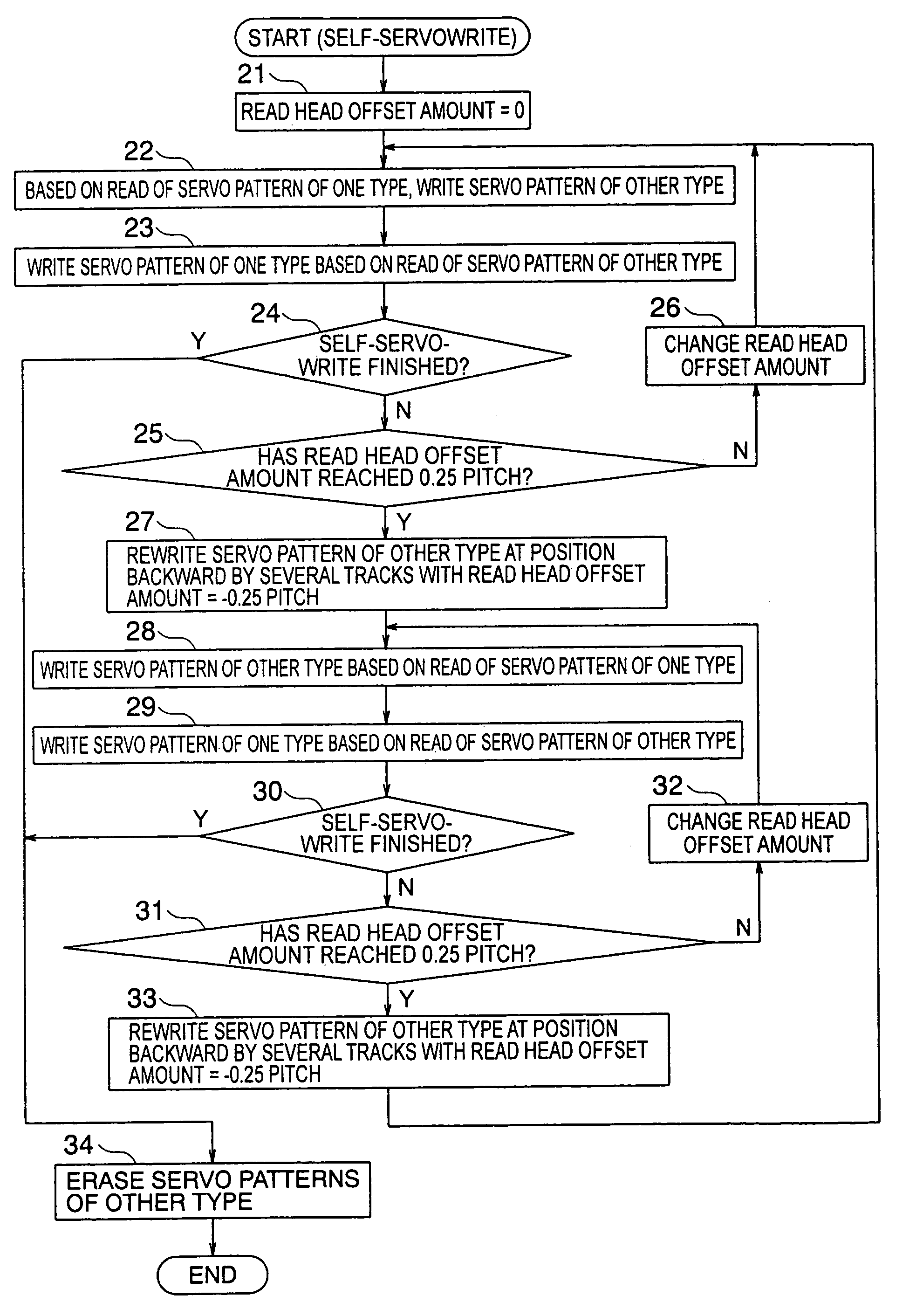
[0035]Further, as a mode of an embodiment of the servo pattern write method of the present invention, the method may further include erasing the ...


PUM

PropertyMeasurementUnit
widthaaaaaaaaaa
timeaaaaaaaaaa
structureaaaaaaaaaa

Abstract

Disclosed are a disc apparatus and a servo pattern write method thereof. The disc apparatus includes a disc having: a first servo pattern formed of burst patterns and written to have predetermined repetition patterns in a radial direction; and second servo pattern having a first repetition pattern portion and a second repetition pattern portion that are alternately arranged in the radial direction, the first repetition pattern portion having the same repetition patterns as the repetition patterns of the first servo pattern and written at a position deviated in the radial direction from the first servo pattern by approximately one fourth of the radial direction width of the burst pattern, and the second repetition pattern portion having the same repetition patterns as the repetition patterns of the first servo pattern and written at a position with substantially no deviation in the radial direction from the first servo pattern.

Description

CROSS-REFERENCE TO RELATED APPLICATIONS[0001]This application is based upon and claims the benefit of priority from the prior Japanese Patent Application No. 2004-50268, filed on Feb. 25, 2004; the entire contents of which are incorporated herein by reference.BACKGROUND[0002]1. Field of the Invention[0003]The present invention relates to a disc apparatus having a disc with servo information written thereon and a method of writing servo patterns on the disc, and more particularly, to a disc apparatus that itself is capable of writing the servo information (i.e., that has a self-servowrite capability) and a servo pattern write method thereof.[0004]2. Description of the Related Art[0005]Precision improvement in positioning a write head at the time of self-servowrite is indispensable for writing detailed servo information. Conventional arts related to the positioning of a read head necessary for positioning a write head include those described in Japanese Patent Laid-open Application No...

Claims


Application Information

Patent Timeline
Patent Type & Authority Patents(United States)
IPC IPC(8): G11B5/09G11B5/596G11B21/10
CPCG11B5/59666G11B5/59633
Inventor SADO, HIDEO
Owner KK TOSHIBA
Why Eureka
Try Eureka