
Cosmetics brush

Inactive Publication Date: 2006-09-05
BYUN YOUNG KWANG
View PDF17 Cites 53 Cited by
  • Summary
  • Abstract
  • Description
  • Claims
  • Application Information

AI Technical Summary

Benefits of technology

[0009]In order to solve the above-described problems, it is an object of the present invention to provide a cosmetics brush capable of refilling cosmetics liquid in which the lower part of an inner body whose upper part is thread coupled by a coupler and that includes a sealing ring in the inside thereof is pressed so that the cosmetics liquid stored in the inner body is discharged to the brush through liquid guiding passages and a discharge hole formed in a discharger and a liquid transporting tube due to the air pressure generated while the inner body ascends and descends to let a user apply make-up and in which the inner body thread coupled by the coupler can be separated when cosmetics liquid is exhausted so that the inner body is refilled.
[0010]Also, it is another object of the present invention to provide a cosmetics brush capable of easily filling cosmetics liquid and of easily assembling a container by reducing the package units of the cosmetics brush to be supplied to a company.

Problems solved by technology

However, since the conventional cosmetics brush is composed of independent parts that are connected to each other, the number of parts that constitute the cosmetics brush is large so that manufacturing expenses increase.
In particular, when the independent parts are connected to each other, it is difficult to keep the parts tightly sealed up so that it is difficult to reduce a defective proportion to no more than a predetermined level.
Also, since the number of parts that constitute the cosmetics brush is so large that assembling and manufacturing processes are complicated and that the parts assembled in minimum package units are assembled in package units of no less than four parts to be supplied to a company before filling cosmetics liquid, the number of parts to be assembled after filling the cosmetics liquid is large so that assembling processes are complicated.

Method used


Image

  • Cosmetics brush
  • Cosmetics brush
  • Cosmetics brush

Examples


Embodiment Construction

[0016]Hereinafter, preferred embodiments of the present invention will be described with reference to the accompanying drawings.

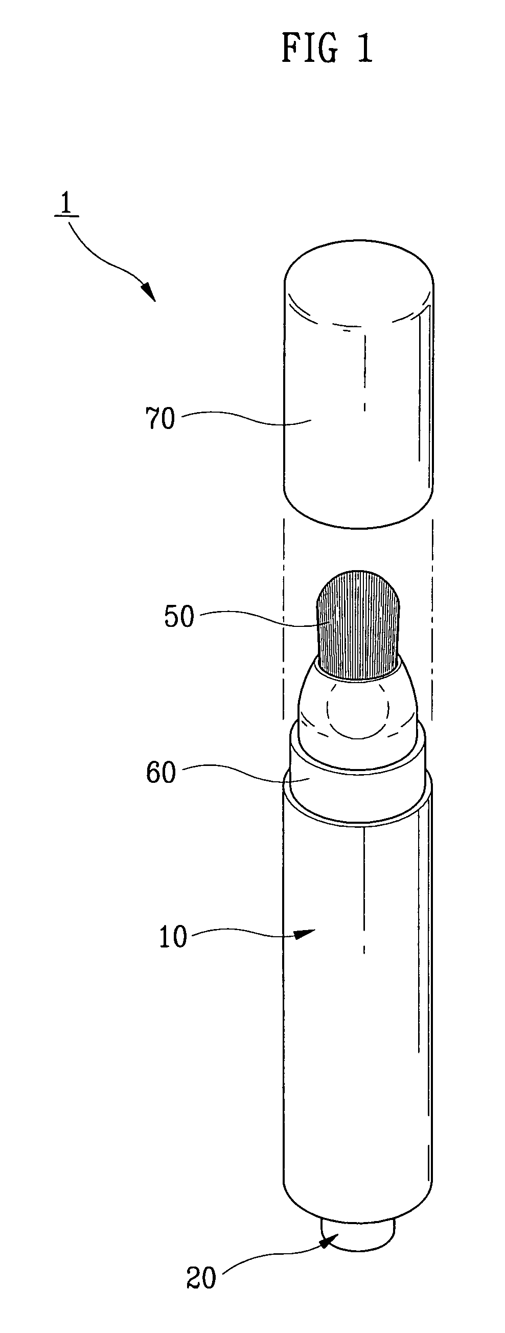
[0017]FIG. 1 is a perspective view of a cosmetics brush according to the present invention. FIG. 2 is an exploded perspective view of the cosmetics brush according to the present invention. FIG. 3 is a sectional view of the cosmetics brush illustrated in FIG. 2. FIG. 4 is a sectional view illustrating a state in which a discharger ascends.

[0018]The outer body 10 of a cosmetics brush 1 according to the present invention is thread coupled with the upper part of the cosmetics brush 1 by a coupler 30. The lower part of an inner body 20 including a sealing ring 21 in the inside thereof is pressed so that the cosmetics liquid stored in the inner body 20 is properly discharged to a brush 50 through vertical and horizontal liquid guiding passages 42 and 43, a discharge hole 44, and a liquid transporting tube 51 formed in a discharger 40 by the air pressure generate...


PUM


Abstract

A cosmetics brush, and more particularly, to a cosmetics brush in which cosmetics liquid is discharged to a brush using the air pressure generated by pressing an inner body is provided. In the cosmetics brush, the lower part of the inner body whose upper part is thread coupled by a coupler and that includes a sealing ring in the inside thereof is pressed so that the cosmetics liquid stored in the inner body is discharged to the brush through liquid guiding passages and a discharge hole formed in a discharger and a liquid transporting tube due to the air pressure generated while the inner body ascends and descends to let a user apply make-up. Since the inner body thread coupled with the coupler can be separated and refilled with cosmetics liquid when cosmetics liquid is exhausted, the cosmetics brush is economical and convenient.

Description

CROSS-REFERENCE TO RELATED APPLICATIONS[0001]This application claims the benefit of Korean Patent Applications No. 10-2005-0035921 and 10-2005-0095352, filed on Apr. 29, 2005 and Oct. 11, 2005, respectively in the Korean Intellectual Property Office, the disclosures of which are incorporated herein by reference.BACKGROUND[0002]1. Field of the Invention[0003]The present invention relates to a cosmetics brush, and more particularly, to a cosmetics brush to which cosmetics liquid is discharged using air pressure generated by pressing an inner body. The lower part of the inner body whose upper part is thread coupled by a coupler and that includes a sealing ring in the inside thereof is pressed so that the cosmetics liquid stored in the inner body is discharged to the brush through liquid guiding passages and a discharge hole formed in a discharger and a liquid transporting tube due to the air pressure generated while the inner body ascends and descends to let a user apply make-up. The i...

Claims


Application Information

Patent Timeline
IPC IPC(8): A46B11/04
CPCA45D34/042A46B11/0041B05B11/307B05B11/0064B05B11/3015B05B11/3052A46B2200/1046B05B11/0037B05B11/0048B05B11/0038B05B11/1015B05B11/028B05B11/107B05B11/1052
Inventor BYUN, YOUNG KWANG
Owner BYUN YOUNG KWANG
Learn More