
Signal connection for a downhole tool string

a technology of signal connection and tool string, which is applied in the direction of instruments, borehole/well accessories, surveys, etc., can solve the problems of similar obstacles, unfavorable commercial success of proposals, and the environment is equally harsh for electronic components

Active Publication Date: 2006-08-29
INTELLISERV
View PDF120 Cites 24 Cited by
  • Summary
  • Abstract
  • Description
  • Claims
  • Application Information

AI Technical Summary

Benefits of technology

[0007]A top-hole signal connection for a tool string for drilling oil, gas, and geothermal wells is presented. This invention may also be used in connection with production wells. The invention enables signal transmission during drilling for and production of energy resources as well as during periods when drilling and production are interrupted. The connection comprises annular elements deployed in association with drilling and production equipment. In a drilling application, the connection apparatus is mounted on the drill rig. In production applications, the apparatus is mounted on the well head. The first element of the apparatus is fixed to the drill rig or well head while the rotational second element is fixed to the tool string. The fixed and rotating elements comprise inductive transducers that are capable of two-way signal transmissio...

Problems solved by technology

These proposals have not met with commercial success for reasons associated with the numerous technological obstacles that must be hurdled in order to achieve efficient and reliable connections across the hundreds of tool string components that are required to successfully reach and acquire the underground energy resources.
In a production well similar obstacles are present.
Additionally, high temperatures, fluids and corrosive gases mixed with abrasive particles combine to make the production environment an equally harsh environment for electronic components.

Method used


Image

  • Signal connection for a downhole tool string
  • Signal connection for a downhole tool string
  • Signal connection for a downhole tool string

Examples


Embodiment Construction

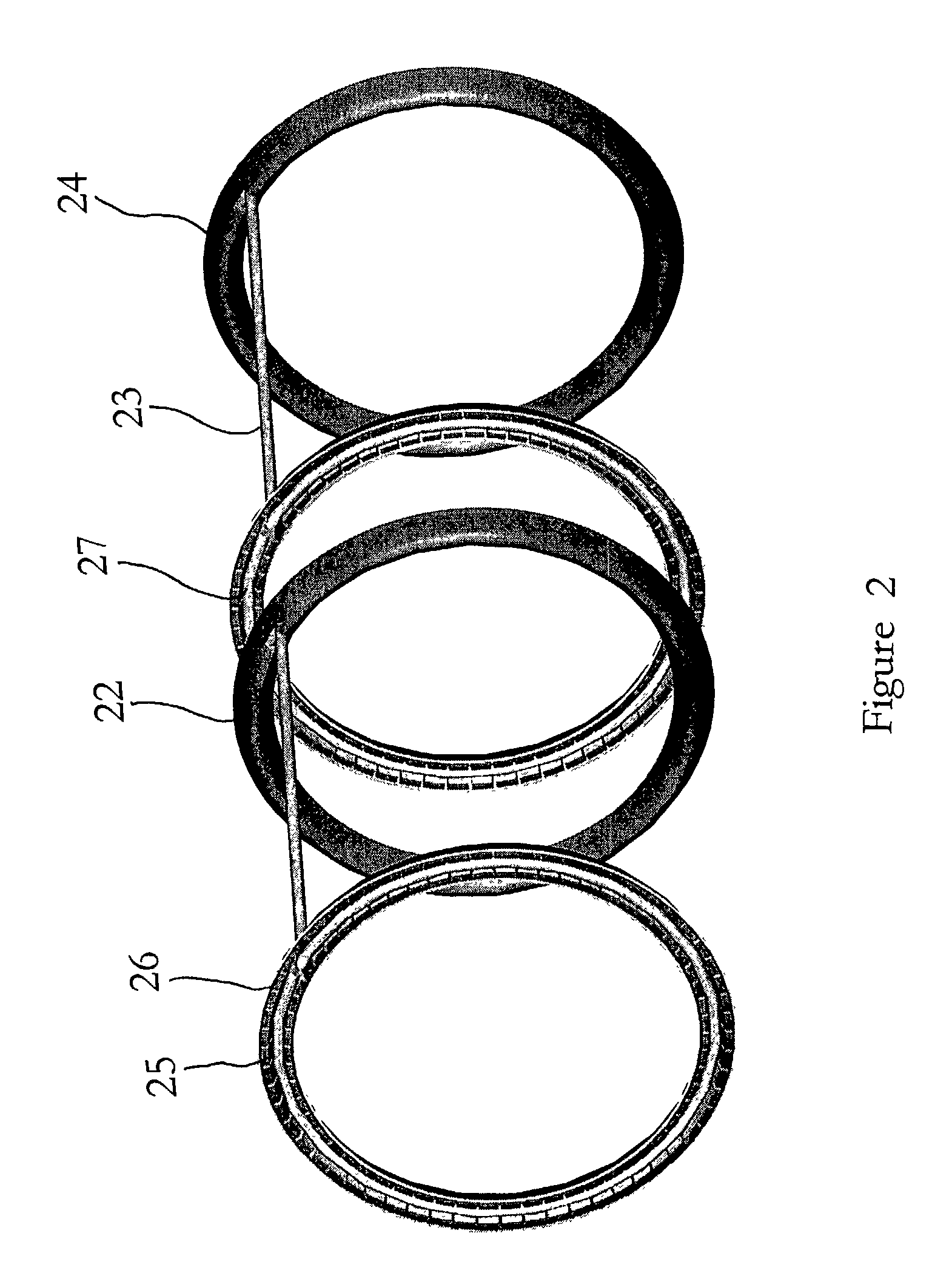
[0015]A top-hole swivel connection apparatus is presented that is adapted for the transmission of an electronic signal to and from a tool string used in the drilling of an oil, gas, or geothermal well. This invention also has application in production wells. The invention will be better understood in reference to the following detailed descriptions of the drawings. The drawings are presented by way of illustration only and are not intended to limit the bounds of the present invention. Those skilled in the art are likely to identify additional applications for the present invention. Such additional applications are included within the scope of this disclosure.

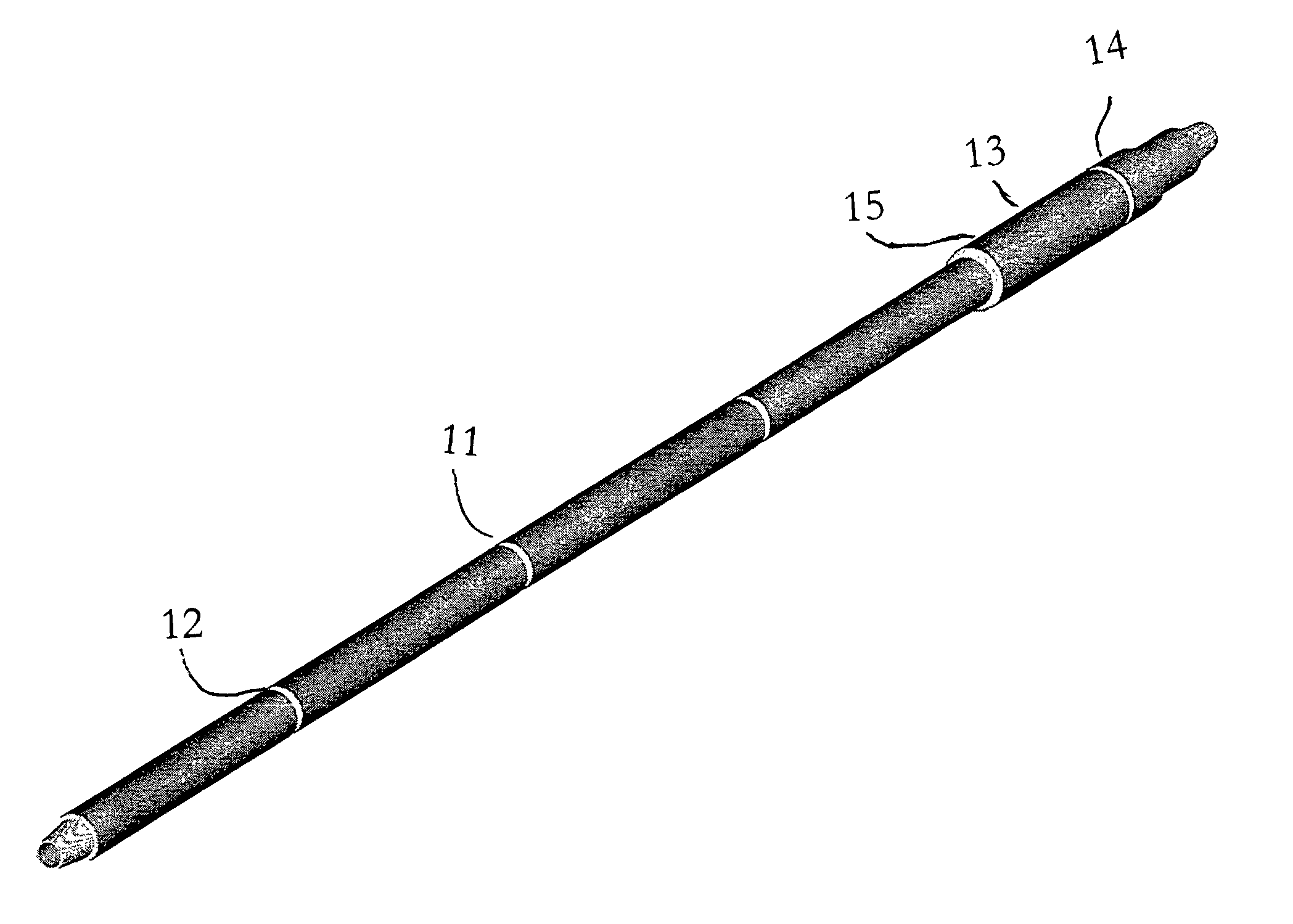
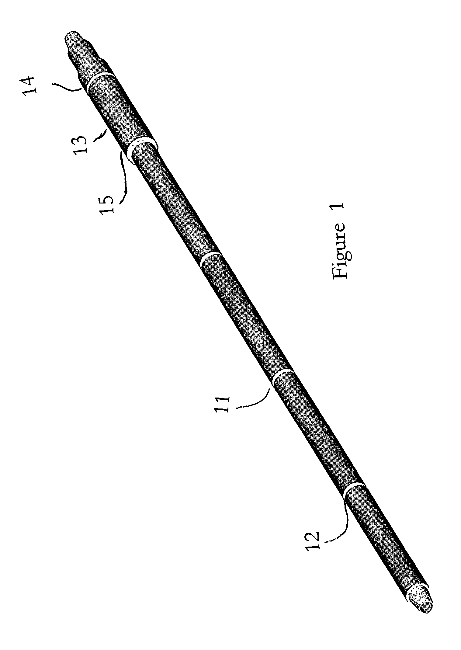
[0016]FIG. 1 is a perspective diagram of a portion of a tool string. The diagram is presented without reference to the drill rig or production head for clarity. The tool string is made up of annular segments 11 that are joined together at threaded tool joints 12. In reference to a production well, the tool string is made up of w...


PUM


Abstract

A signal transmission connection for a tool string used in exploration and production of natural resources, namely: oil, gas, and geothermal energy resources. The connection comprises first and second annular elements deployed in cooperative association with each other. The respective elements comprise inductive transducers that are capable of two-way signal transmission between each other, with downhole components of the tool string, and with ground-level equipment. The respective inductive transducers comprise one or more conductive loops housed within ferrite troughs, or within ferrite trough segments. When energized, the conductive loops produce a magnetic field suitable for transmitting the signal. The second element may be rotational in drilling applications. The respective elements may be fitted with electronic equipment to aid and manipulate the transmission of the signal. The first element may also be in communication with the World Wide Web.

Description

[0001]This invention was made with government support under Contract No. DE-FC26-01NT41229 awarded by the U.S. Department of Energy. The government has certain rights in the invention.BACKGROUND OF THE INVENTION[0002]Generally, this invention relates to the transmission of a signal in association with all or part of a tool string used in drilling oil, gas, and geothermal wells and for all or part of a tool string used in a production well. More particularly, this invention relates to a connection apparatus comprising fixed and rotating inductive transducers that are in communication with each other, a network of downhole inductive transducers along the tool string, and with ground-level equipment, including the World Wide Web.[0003]For more than 50 years proposals have been made for transmitting an electronic signal along the length of the tool string used in the exploration and production of useful hydrocarbons and subterranean energy sources, namely oil, gas, and geothermal energy...

Claims


Application Information

Patent Timeline
IPC IPC(8): G01V3/00E21B47/00G08C19/16G01V11/00
CPCG01V11/002
Inventor HALL, DAVID R.HALL, JR., H. TRACYPIXTON, DAVID S.BRADFORD, KLINEFOX, JOEBRISCOE, MICHAEL
Owner INTELLISERV
Learn More