Adjustable spring grounding pin

Inactive Publication Date: 2006-08-29
NIDEC MOTOR CORP
View PDF2 Cites 0 Cited by
  • Summary
  • Abstract
  • Description
  • Claims
  • Application Information

AI Technical Summary

Benefits of technology

[0010]The pin has a cylindrical exterior surface that extends longitudinally between opposite first and second end faces of the pin, and a hollow interior bore extending through the center of the pin from the first end face to the second end face. The exterior surface of the pin has an outer diameter that is dimensioned to fit in tight friction engagement with the hole drilled through the end shields of the motor, even when that hole is slightly larger than the hole drilled into the stator of the motor. The construction of the pin center bore allows the opposite ends of the pin to contract or collapse radially inwardly independently of each other. With this construction, when the stator hole is smaller than the hole of the end shields, the end of the pin driven into the stator hole will collapse to a greater extent than the end of the pin that remains in the hole of the end shields. In this manner, both ends of the pin of the invention engage in a tight friction engagement with the stator hole and the hole of the end shields, and the pin provides a proper ground between the separate component parts of the motor.
[0012]A longitudinally extending slot is formed in the pin from its exterior surface through to the pin center bore. The slot intersects the opposite end faces of the pin. The slot gives the pin a cross section resembling a c-spring. The slot, together with the hollow center bore of the pin enables the pin to collapse on itself as it is driven through the hole of the end shields and into the hole of the stator.
[0013]In the preferred embodiment, a transverse notch is also formed into the exterior surface of the pin intermediate the opposite end faces of the pin. The notch extends across the longitudinal slot of the pin and intersects the pin center bore. The notch isolates the longitudinally opposite ends of the pin and prevents the collapsing of the pin end driven into the stator hole from influencing the collapsing of the pin end driven into the hole of the end shields.

Problems solved by technology

This prior art method of grounding motor parts was found to be disadvantaged in that, because the metal of the end shields, and in particular the end shield legs 22, 24, is usually softer than the metal of the laminations of the stator 16, when the hole is formed through the end shield legs and into the stator it would often result in the hole 28 through the end shield legs being slightly larger than the hole 32 formed in the stator.

Method used


Image

  • Adjustable spring grounding pin
  • Adjustable spring grounding pin
  • Adjustable spring grounding pin

Examples


Embodiment Construction

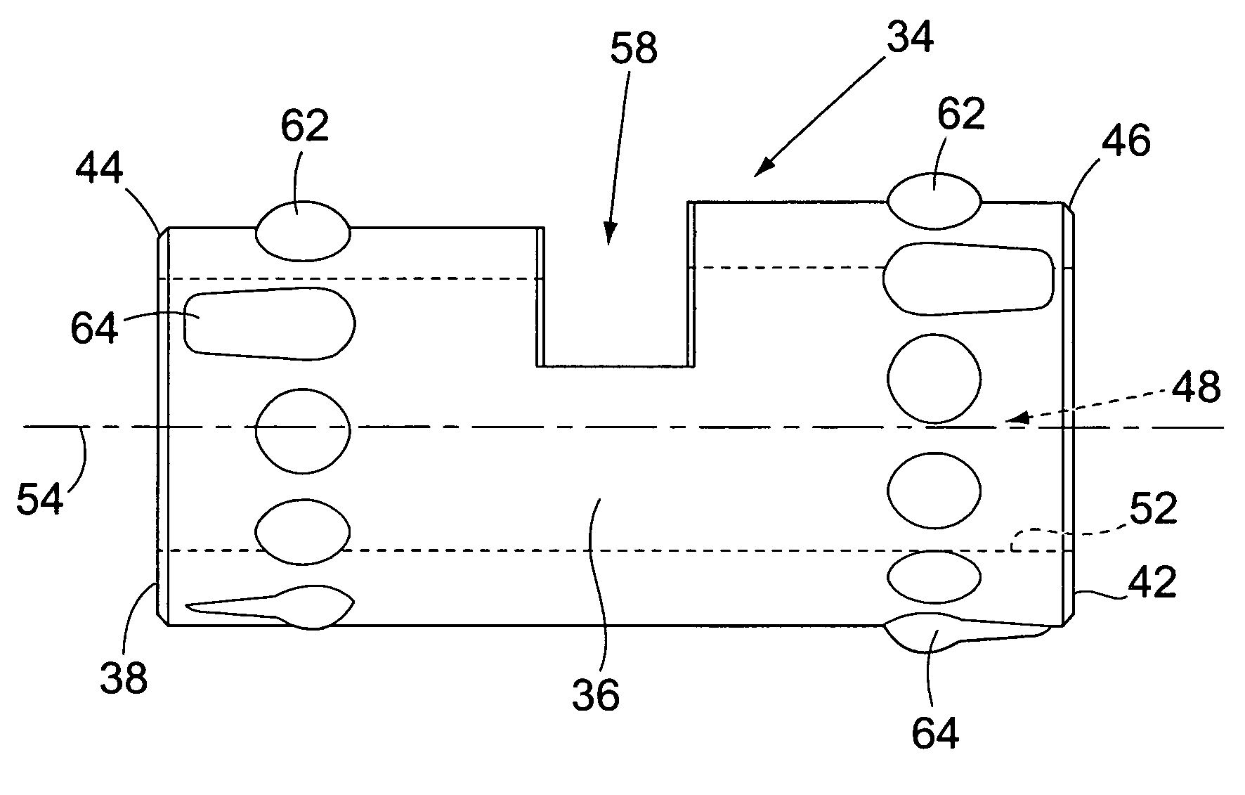
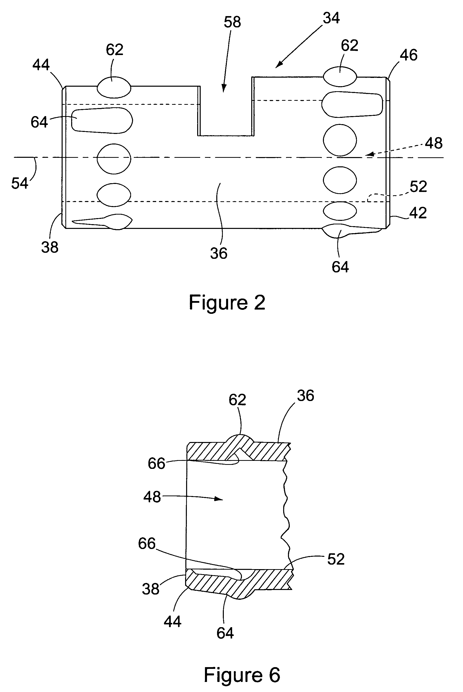
[0022]FIGS. 2 and 3 show respective side and top views of the grounding pin 34 of the invention. In the preferred embodiment, the pin is constructed of a metal having a hardness that is greater than that of the laminations of the stator into which the pin is to be driven. The metal of the grounding pin is also harder than the metal employed in forming the end shields of the motor. Preferably, the metal is spring steel.

[0023]The grounding pin 34 is constructed with a cylindrical exterior surface 36 that extends longitudinally between axially opposite first 38 and second 42 end faces of the pin. The exterior diameter of the pin is determined to provide a tight friction engagement with the hole to be drilled into the end shields and stator laminations of the motor (not shown) with which the pin is used. The pin is formed with tapered portions 44, 46 adjacent the opposite end faces 38, 42 of the pin. The tapered portions are provided to assist in aligning the pin with the holes of the e...


PUM


Abstract

An adjustable spring grounding pin for grounding separate parts of an electrical device, for example end shields and a stator of an electric motor, automatically adjusts its circumferential dimension to provide a tight grounding fit between aligned holes of different interior diameters in the end shields and the stator of the device as the grounding pin is driven into the aligned holes.

Description

BACKGROUND OF THE INVENTION[0001](1) Field of the Invention[0002]The present invention pertains to an adjustable spring grounding pin for grounding three separate parts of an electrical device, for example two end shields and a stator of an electric motor. In particular, the invention pertains to a grounding pin that automatically adjusts its circumferential dimension to provide a tight grounding fit between aligned holes of different interior diameters in end shields and a stator of an electrical device as the grounding pin is driven into the aligned holes.[0003](2) Description of the Related Art[0004]An electrical device such as an electric motor typically includes the basic component parts of a stator, a pair of end shields mounted over axially opposite ends of the stator, and a rotor. The rotor is positioned in a center bore of the stator with opposite ends of the rotor shaft being mounted for rotation in bearings or bushings in the opposite end shields of the motor.[0005]FIG. 1...

Claims


Application Information

Patent Timeline
Patent Type & Authority Patents(United States)
IPC IPC(8): H05K5/02
CPCH02K11/0089H02K5/225H02K11/40
Inventor WADE, III, CLIFTONDOHOGNE, L. RANNEYLEWIS, WILLIAM R.
Owner NIDEC MOTOR CORP
Why Eureka
Try Eureka