
Heated compule

a compulsive and material heating technology, applied in the field of compulsive, can solve the problems of long heating time, time-consuming procedure, short heating time, etc., and achieve the effect of reducing heating time, reducing heating time, and much more efficient heating

Active Publication Date: 2006-08-29
FRIEDMAN JOSHUA
View PDF3 Cites 27 Cited by
  • Summary
  • Abstract
  • Description
  • Claims
  • Application Information

AI Technical Summary

Benefits of technology

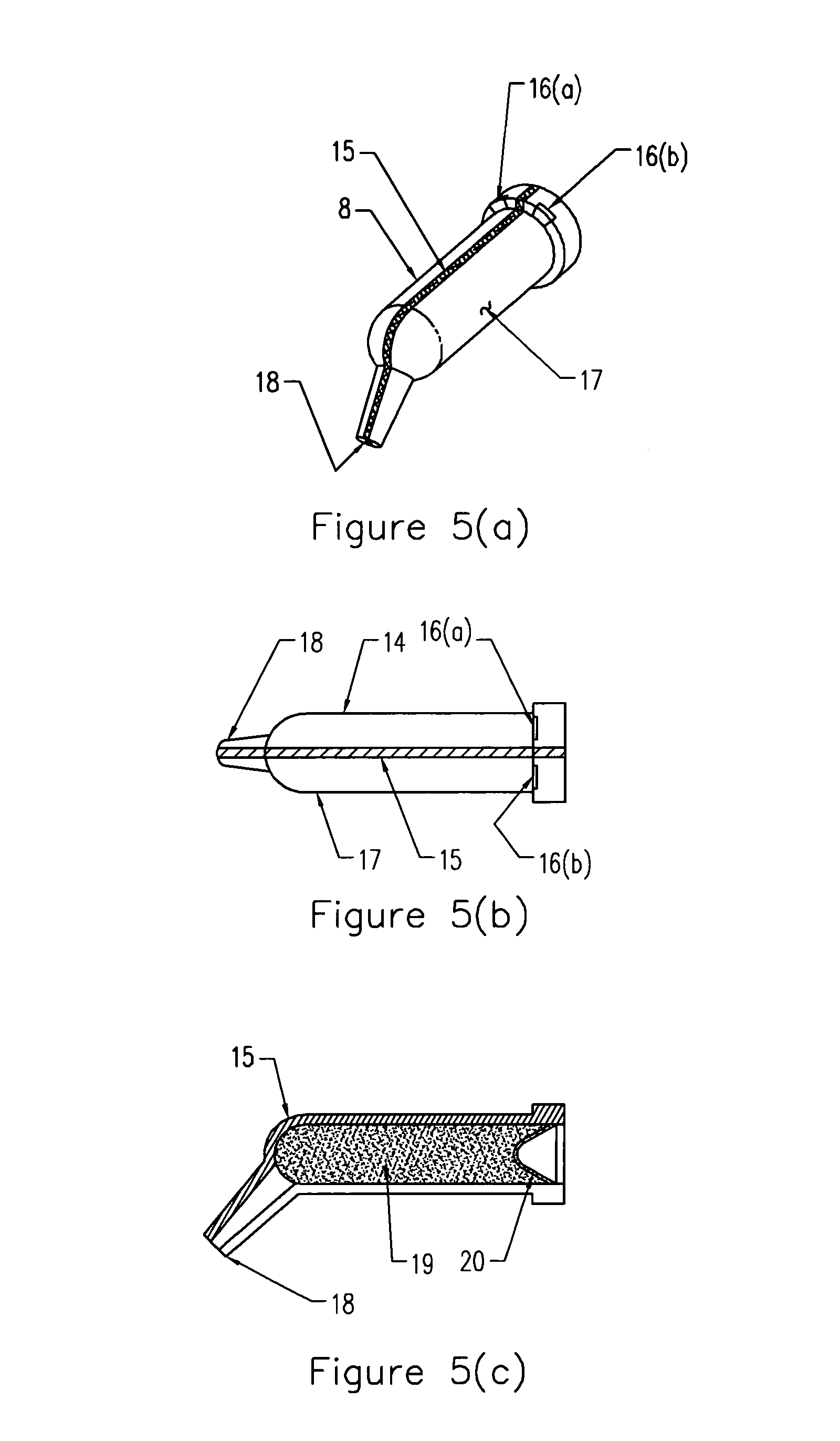
[0013]An improved compule of the present invention incorporates a molded in (insert molded) heating means into the thermally conductive body of the compule so that the compule will be both thermally conductive and electrically conductive. In a preferred embodiment, the plastic itself is made from a class of materials, which is both thermally and electrically conductive with electrical conductivity measured as resistivity in the range 0.01–10,000 ohm-cm. One such material may be the COOLPOLY E5101 a trademark product of Cool Polymers, Inc. USA for a polymeric composition which is both electrically and thermally conductive. In this preferred embodiment the heating material is formed into distinct sections, i.e., half sections (although it is not critical that each section be identical in size) which surround the body of the compule or define the body of the compule and an electrical current is passed through both halves of the compule so that the plastic itself will heat up. Since the compule is now itself the heating element, heating is much more efficient and the material heats significantly faster.
[0014]Using this arrangement, there is more than an order of magnitude (i.e. 10 seconds compared to 180 seconds) reduction in heating time. In addition, the power required is far less, making the dispensing device, smaller, less costly and easier to handle.

Problems solved by technology

While these methods work for introducing heated composite materials into the mouth, they suffer from several drawbacks.
In the case of heating a syringe, a large bulk of material is heated needlessly, and the heating time is long.
In the case of heating a compule (dose package), the heating time is shortened but still significantly long.
In the case of heating material expressed from a syringe onto a heated surface, the material needs to be first picked up, then introduced into the dental cavity and then repeated with each layer, also in a time consuming procedure.

Method used


Image

  • Heated compule
  • Heated compule
  • Heated compule

Examples


Embodiment Construction

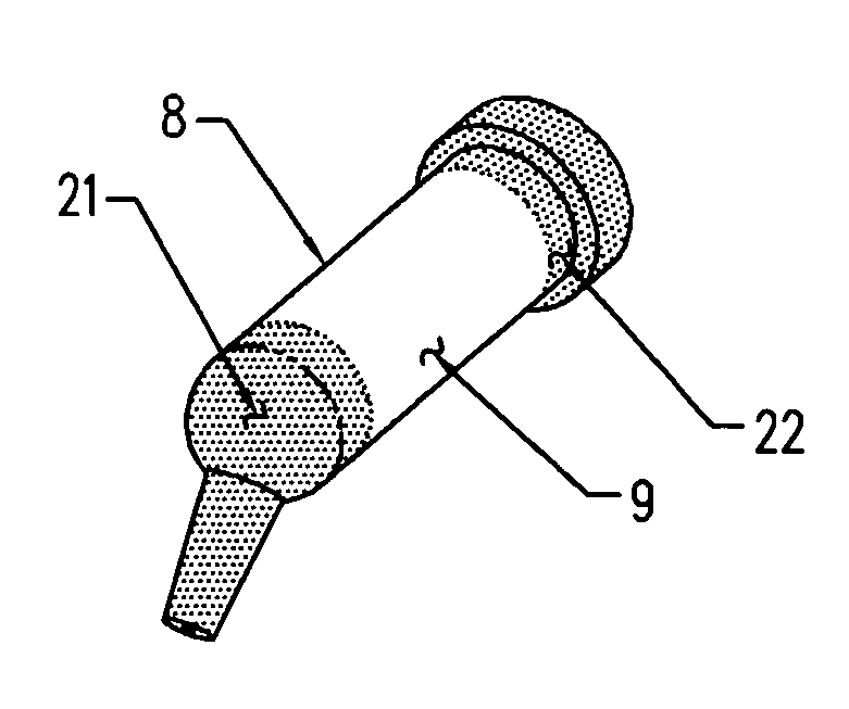
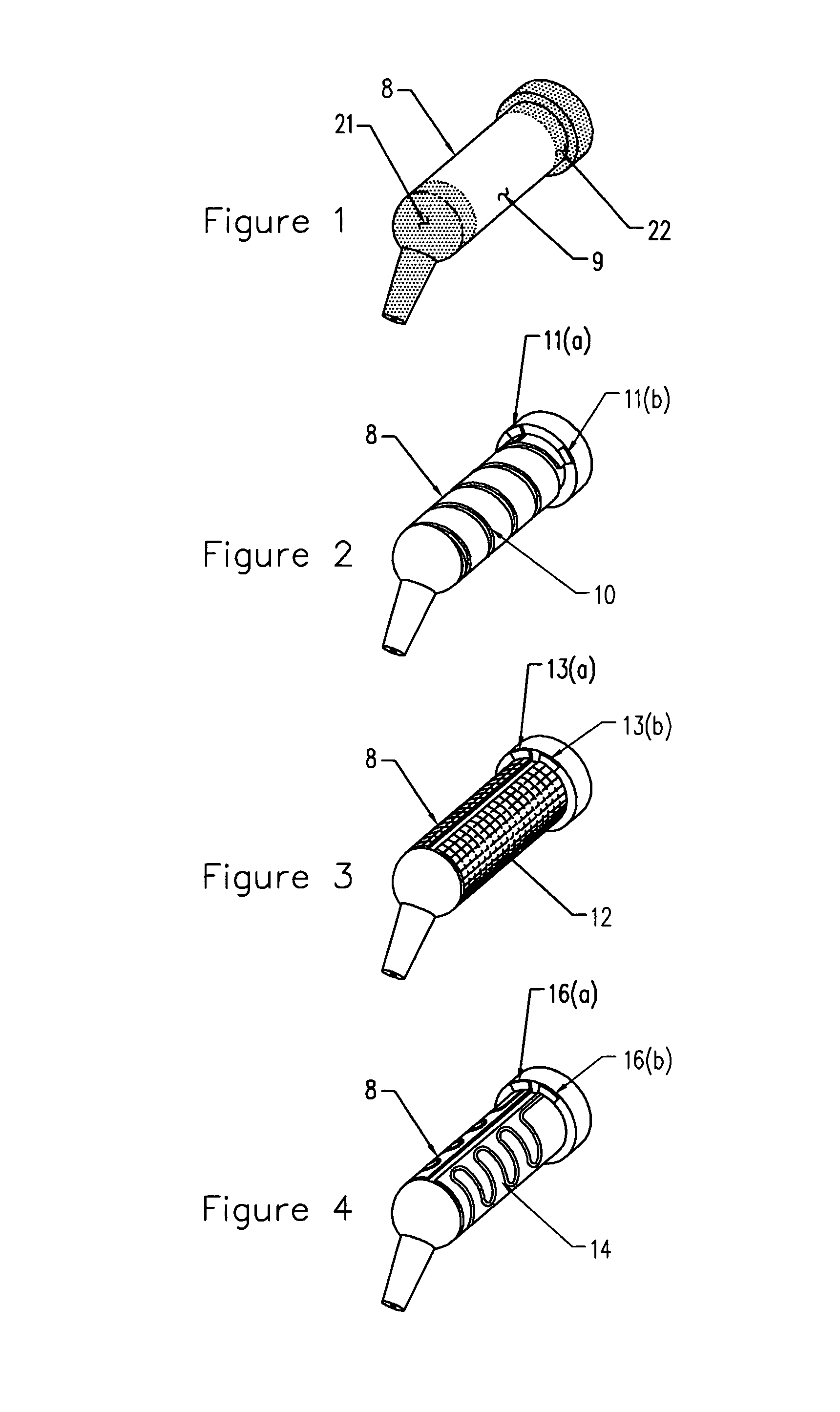
[0021]FIG. 1 is a perspective view of the compule (8) of the present invention with the body (9) of the compule (8) composed of thermally conductive plastic having a thermal conductivity in the range from 1.0 w / mk to 500 w / mk. It should be understood that the word compule is be interpreted broadly for purpose of the present application to represent any conventional container to store dental material such as dental composite adapted for use with a standard dispensing device to express the dental material from the compule and includes that of a dental syringe.

[0022]FIG. 1 also shows the use of an electrically conductive material to form the body (9) of compule (8). The body material (9) has a resistivity in the range of 0.01–10,000 ohm-cm. Once electrical contact is made anywhere on or along the distal area (21) adjacent the dispensing end of the compule (8) and the other electrical contact is made anywhere on or along the proximal area (22). The areas 21 and 22 are identified in FIG....


PUM

PropertyMeasurementUnit
timeaaaaaaaaaa
resistivityaaaaaaaaaa
thermal conductivityaaaaaaaaaa

Abstract

A compule for storing dental composite material to be extruded from the compule using a standard dispenser in the preparation or repair of a dental restoration. The compule comprises: a cylindrical body having an orifice at one end thereof through which the dental composite material is extruded and a means at the opposite end thereof to facilitate the extrusion of said dental composite material using the dispenser. The body of the compule is composed of an electrically conductive plastic or alternatively may be composed of a thermally and electrically conductive plastic having a thermal conductivity in the range of between 1.0 w / mk and 500 w / mk and an electrical resistivity in the range 0.01–10,000 ohm-cm.

Description

FIELD OF INVENTION[0001]This invention is a continuation in part of U.S. patent application Ser. No. 10 / 783,924 filed Feb. 20, 2004 and relates to a compule for storing dental composite material and more particularly to a dental compule which is thermally conductive and preferably also electrically conductive so that the composite material can be heated quickly by direct heat transfer upon heating the compule.BACKGROUND[0002]Light cured materials have become regularly used in dentistry. The advantages of light curing a one-part material over a two-part system are well documented. The ability to cure on command offers the dental practioner a wide degree of control over the shape and shade of a dental restoration. This inventor has discussed various methods of delivering heated dental materials, which because of the heating effect causes these materials to take on superior handling characteristics as well as improved physical properties in the polymerized state.[0003]In the case of de...

Claims


Application Information

Patent Timeline
Patent Type & Authority Patents(United States)
IPC IPC(8): A61C5/04A61C5/06
CPCA61C5/062A61C5/066B05C17/00516A61C5/62A61C5/66
Inventor FRIEDMAN, JOSHUA
Owner FRIEDMAN JOSHUA
Learn More