Screen printing apparatus having paste chamber with discharge opening and structure for introducing paste residue from previous printing into discharge opening

a technology of a discharge opening and a discharge opening, which is applied in the direction of printing, office printing, coating, etc., can solve the problems of uneconomic disposal of reusable paste residue, unfavorable cleaning and maintenance, and liquid flux including solder particles leakage between the scraper or the blade and the screen, etc., to facilitate cleaning and maintenance, inspection, and easy disassembly

Inactive Publication Date: 2006-08-29
TANI ELECTRONICS IND CO LTD
View PDF8 Cites 13 Cited by
  • Summary
  • Abstract
  • Description
  • Claims
  • Application Information

AI Technical Summary

Benefits of technology

[0009]To attain the above-mentioned main object of the present invention, there is provided in accordance with the invention a screen printing apparatus having a housing-like main body that is long sideways, characterized in that inside the main body, there are provided a paste accommodation chamber and a roller pivotally mounted along the axis of the main body that a discharge opening that is long sideways and serves to discharge the paste accommodated in the accommodation chamber onto the upper surface of a screen placed on a board is formed at the bottom of the main body between a scraper that projects forward and diagonally downward and whose tip slides on the screen upper surface during printing while being in contact therewith and a guide plate that is opposed to the scraper and projects backward and diagonally downward and whose tip ends at such a height where a predetermined gap is maintained from the tip to the screen upper surface during printing, so that as the main body is moved forward, that is, in a printing direction and the roller is rotated in one direction, the paste can be filled in pattern holes of the screen by fluid pressure of the paste discharged from the discharge opening, and that a front wall of the main body is formed with a space for introducing a residue of the paste adhered to the screen upper surface in the preceding printing to the discharge opening through said gap in each printing so that the paste residue is mixed into the paste discharged from the discharge opening and can be used for printing.
[0012]Furthermore, there is provided in accordance with the invention a screen printing apparatus, characterized in that the roller is disposed close to the discharge opening so as to be in sliding contact with a low projection strip that projects from the scraper parallel with the axis of the roller, and forms, between said projection strip itself and a guide surface of the guide plate, a narrow guide passage that serves to increase paste discharge pressure.

Problems solved by technology

In the screen printing performed by using such a known type of screen printing apparatus, it is unavoidable that the liquid flux including solder particles leaks out from between the scrapers or blades and a screen during printing and remains on the screen for, for example, the following reasons: a desired number of printing operations are repeated automatically; in general, screens have deformed portions and small asperity; and solder particles and flux as components of the solder paste tend to be separated from each other by shearing force generated by the discharge pressure exerted on the solder paste during printing.
However, solder paste is as expensive as 50,000 to 300,000 yen per 100 g and accordingly, disposal of reusable paste residue is uneconomical.
Moreover, printing operations need to be suspended during a cleaning operation, which causes the efficiency of the printing operations to be lowered.

Method used


Image

  • Screen printing apparatus having paste chamber with discharge opening and structure for introducing paste residue from previous printing into discharge opening
  • Screen printing apparatus having paste chamber with discharge opening and structure for introducing paste residue from previous printing into discharge opening
  • Screen printing apparatus having paste chamber with discharge opening and structure for introducing paste residue from previous printing into discharge opening

Examples


Embodiment Construction

[0030]The present invention will be hereinafter described in detail with reference to the accompanying drawings that illustrate embodiments of the invention.

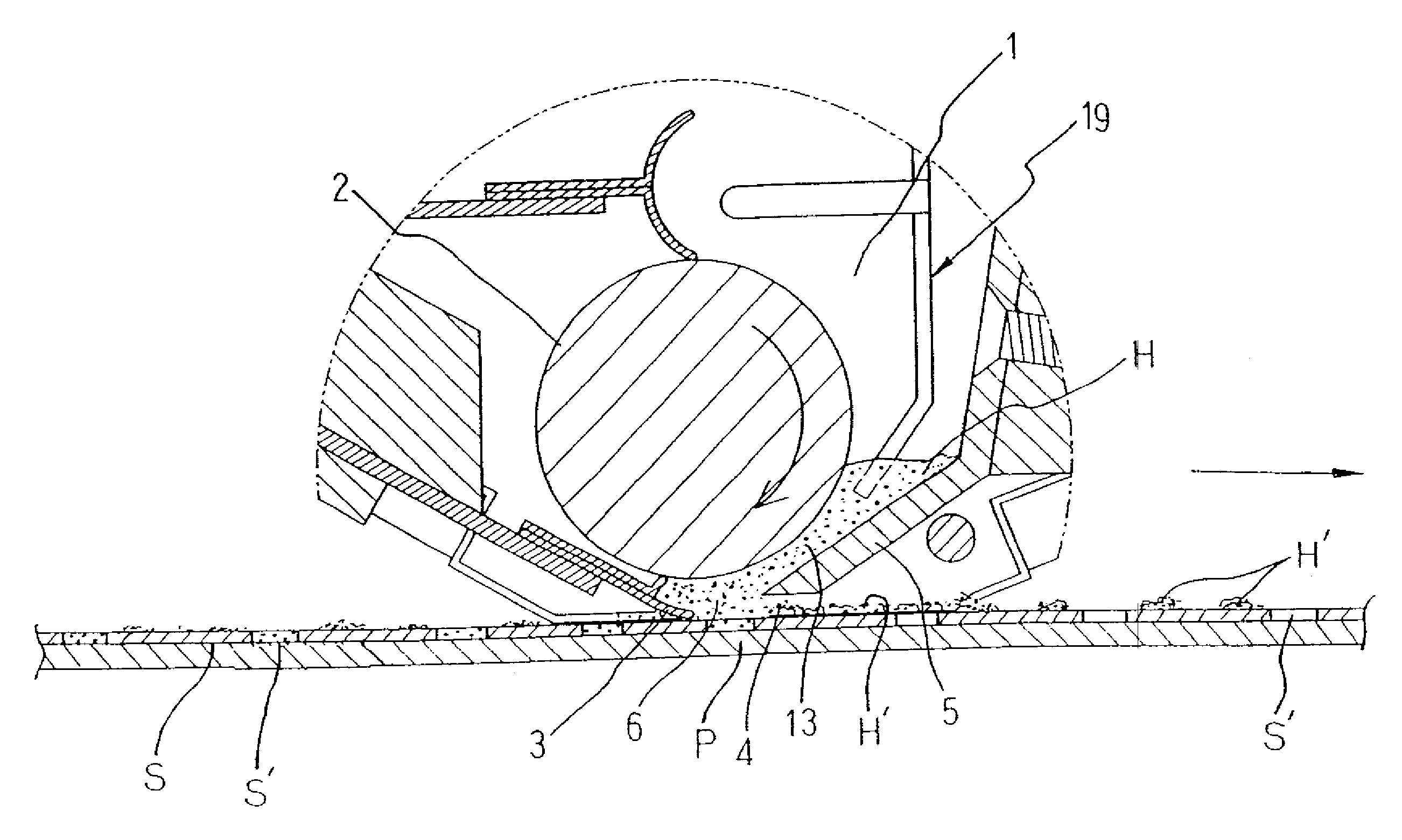
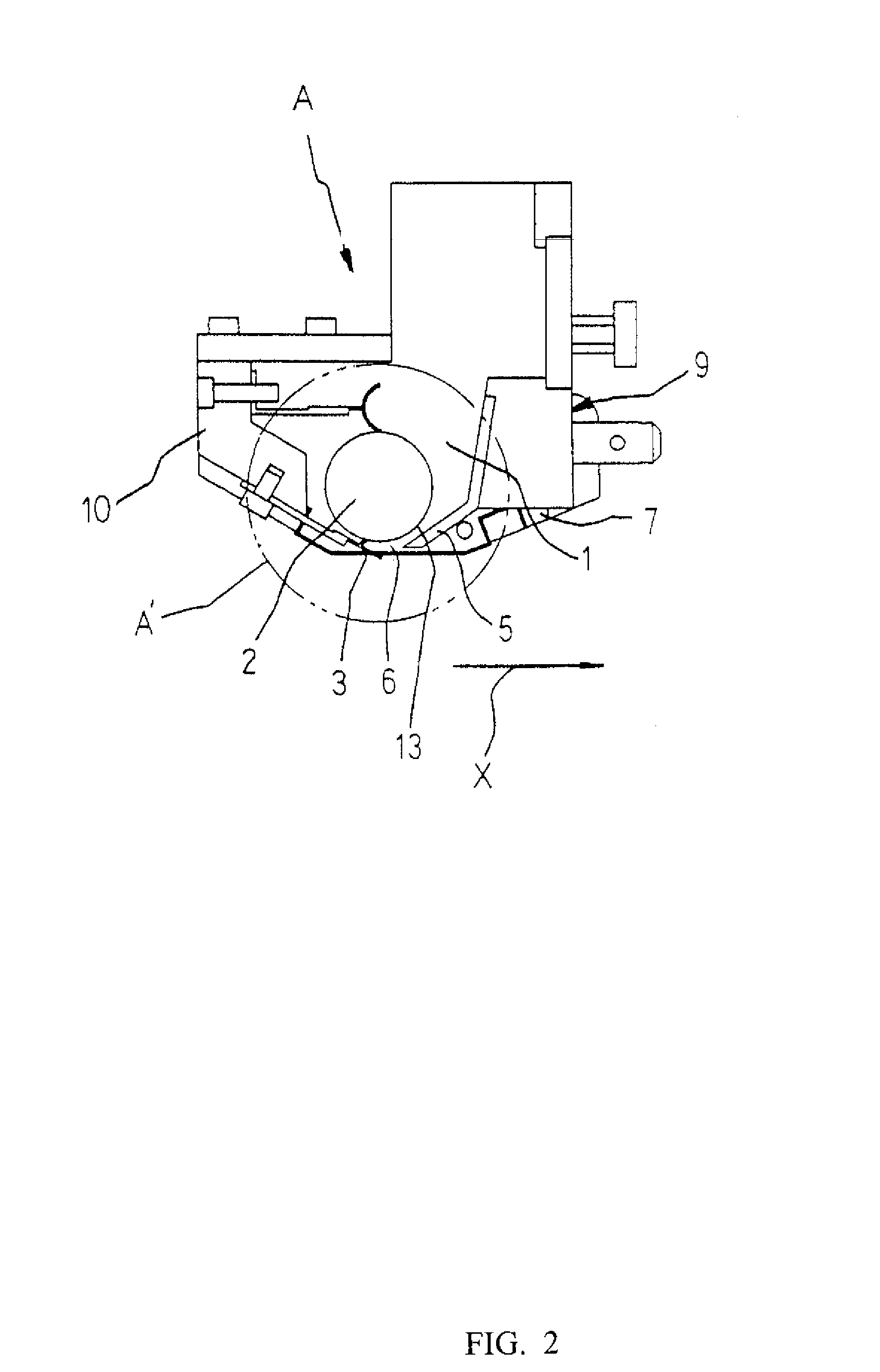
[0031]In the drawings in FIGS. 1–4, reference character A denotes a housing-like main body, long sideways, of a screen printing apparatus. In the main body A, there are provided an accommodation chamber 1 for accommodating solder paste H and a roller 2 pivotally mounted along the axis of the main body. The bottom portion of the main body A has the following structure. A scraper 3 projects forward and diagonally downward and, during printing, whose tip slides on the upper surface of a screen S, which is placed on a board P, while being in contact with said surface. A guide plate 5 extends backward and diagonally downward so as to be opposed to the scraper 3 and, during printing, whose tip terminates at a height where a predetermined gap 4 is maintained from the tip to the upper surface of the screen S. A discharge opening 6, long...


PUM


Abstract

A screen printing apparatus for printing on a board, such as a circuit board, through a screen using a paste prior to surface-mounting electronic components on the board, and more particularly a screen printing apparatus that performs a screen printing while automatically discharging the paste that is accommodated inside the main body.

Description

TECHNICAL FIELD[0001]The present invention relates to a screen printing apparatus for printing on a board, such as a circuit board, through a screen using paste such as solder paste made by kneading a mixture of solder powder and liquid flux, prior to an operation of surface-mounting of electronic components on the board, and more particularly to a screen printing apparatus capable of performing screen printing while automatically discharging, through an opening formed at the bottom of a housing-like apparatus main body, the paste that is accommodated inside the main body.BACKGROUND ART[0002]A screen printing apparatus is known from JP-A-5 (1993)-57870 and U.S. Pat. No. 5,947,022 (Jul. 9, 1999), for example. In the screen printing apparatus of this type, a pair of scrapers or blades is provided inside the apparatus main body so as to be inclined inward and opposed to each other. Solder paste accommodated inside the main body is pushed out of the opening opened between the scrapers o...

Claims


Application Information

Patent Timeline
Patent Type & Authority Patents(United States)
IPC IPC(8): B41F15/42B05C17/005B41F15/46
CPCB41F15/46Y10S101/34
Inventor KATANO, TOMOYAHASHIMOTO, MAKOTO
Owner TANI ELECTRONICS IND CO LTD
Why Eureka
Try Eureka