Sensing mode atomic force microscope

a technology sensing mode, which is applied in the direction of mechanical measurement arrangement, mechanical roughness/irregularity measurement, instruments, etc., can solve the problems of inability to accurately and repeatable measurements, process cannot be observed in real time with electron microscope or x-ray crystallography techniques, and specimen surface, etc., to achieve the effect of improving operability and enabling the use of atomic force microscop

Inactive Publication Date: 2006-08-22
BROOKHAVEN SCI ASSOCS
View PDF4 Cites 2 Cited by
  • Summary
  • Abstract
  • Description
  • Claims
  • Application Information

AI Technical Summary

Benefits of technology

[0013]We have created an advance in the atomic force microscope field which improves operability and / or enables atomic force microscope usability in material science, genomics, proteomics, polymer science, and biomedicine by allowing observation of and data collection from biological specimens in their native environment.
[0017]It is a further object of the present invention to provide an atomic force microscope using a low spring force cantilever which overcomes the problem of probe tip retention resulting from adhesive forces between the probe tip and specimen.
[0019]It is still another object of the present invention to provide an atomic force microscope which is able to generate repeatable scan to scan measurement results on biological specimens.

Problems solved by technology

Currently, these processes cannot be observed in real time with electron microscopes or x-ray crystallography techniques which are known in the art, as the specimens are not in their native environment when using these apparatuses.
Also, when used on soft specimens, such as biological specimens, the probe tip is likely to destroy the surface of the specimen, making accurate and repeatable measurements impossible.
The force that results from tapping mode tends to be destructive to biological specimens.
Also, tapping mode is difficult to use when measuring a fluid-based specimen.
When the cantilever assembly is submerged into a fluid environment, the desired oscillation of the cantilever can be dampened and additional resonances are developed which can adversely affect operation and accuracy.
Also, fluid flow induced by the tapping oscillation tends to erode the specimen.
Because biological specimens tend to reside in a fluid environment, tapping mode is not well suited for measuring these specimens.
Tapping mode is also incapable of separately measuring the contacting force and adhesion force at each pixel.
Because tapping mode cannot separate the two forces, concurrent mapping of each force during scanning is presently not possible with AFM's employing tapping mode.
Such stiff cantilevers, i.e., in the range greater than 0.1 Newtons per meter (N / m), which are required for jump mode, are incompatible with the more sensitive biological specimens which are easily damaged under the application of such forces.
Therefore, it is impossible to measure an adhesion force using this method and difficult to measure the specimen profile at high lateral resolution because of the tip-specimen separation.
Current AFM techniques tend to be destructive to biological specimens.

Method used


Image

  • Sensing mode atomic force microscope
  • Sensing mode atomic force microscope
  • Sensing mode atomic force microscope

Examples


Embodiment Construction

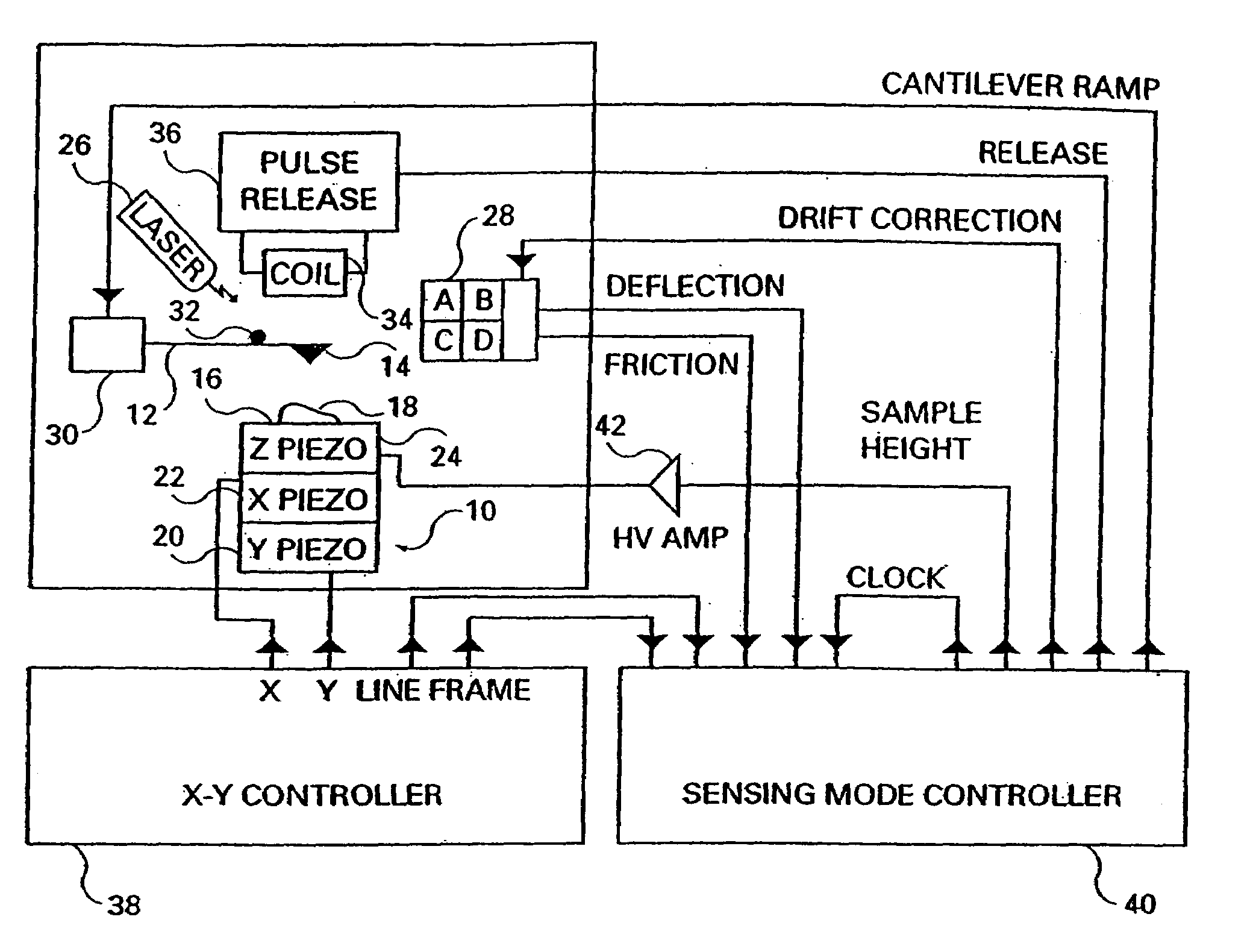
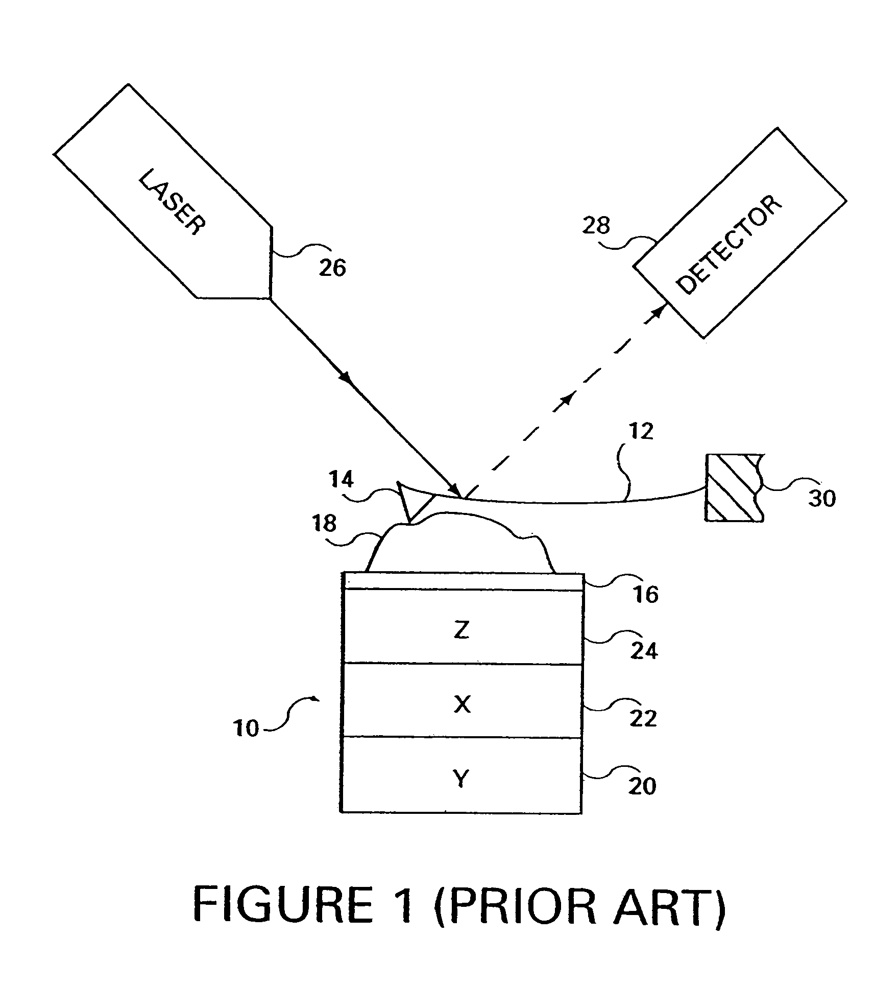
[0043]FIG. 2 is a block diagram generally depicting an atomic force microscope (AFM) formed in accordance with the present invention. The AFM includes a scanner 10 formed in a conventional manner having an X-piezo element 22, a Y-piezo element 20 and a Z-piezo element 24. The scanner 10 has an upper specimen surface 16 on which a specimen 18 to be measured is placed. The X, Y and Z piezo elements each change dimension, in a conventional fashion, in three mutually perpendicular axes, in response to a received control voltage signal. An X-Y controller circuit 38 is included. The X-Y controller circuit 38 controls the X-piezo element 22 and the Y-piezo element 20, generating a conventional raster scan of the specimen surface 16. Several commercially available controllers can provide this function. For example, the NanoScope E controller, manufactured by Digital Instruments, Inc. of Santa Barbara, Calif. is suitable for this application.

[0044]A sensing mode controller circuit 40 is also...


PUM


Abstract

An atomic force microscope is described having a cantilever comprising a base and a probe tip on an end opposite the base; a cantilever drive device connected to the base; a magnetic material coupled to the probe tip, such that when an incrementally increasing magnetic field is applied to the magnetic material an incrementally increasing force will be applied to the probe tip; a moveable specimen base; and a controller constructed to obtain a profile height of a specimen at a point based upon a contact between the probe tip and a specimen, and measure an adhesion force between the probe tip and the specimen by, under control of a program, incrementally increasing an amount of a magnetic field until a release force, sufficient to break the contact, is applied. An imaging method for atomic force microscopy involving measuring a specimen profile height and adhesion force at multiple points within an area and concurrently displaying the profile and adhesion force for each of the points is also described. A microscope controller is also described and is constructed to, for a group of points, calculate a specimen height at a point based upon a cantilever deflection, a cantilever base position and a specimen piezo position; calculate an adhesion force between a probe tip and a specimen at the point by causing an incrementally increasing force to be applied to the probe tip until the probe tip separates from a specimen; and move the probe tip to a new point in the group.

Description

CROSS REFERENCE TO RELATED APPLICATIONS[0001]This is a continuation application which claims the benefit of priority to U.S. application Ser. No. 09 / 591,051, filed Jun. 9, 2000, which issued as U.S. Pat. 6,818,891. U.S. application Ser. No. 09 / 591,051, in turn, which is a continuation in part of and claims the benefit of priority to U.S. application Ser. No. 09 / 054,809, which was filed Apr. 3, 1998 and issued as U.S. Pat. No. 6,518,570.[0002]This invention was made with Government support under contract number DE-AC02-98CH 10886, awarded by the U.S. Department of Energy. The Government has certain rights in the invention.FIELD OF THE INVENTION[0003]The present invention generally relates to the field of atomic force microscopy and, more particularly, to control of an atomic force microscope.BACKGROUND OF THE INVENTION[0004]The present invention relates generally to atomic force microscopy and more particularly relates to an atomic force microscope and controller which minimize conta...

Claims


Application Information

Patent Timeline
Patent Type & Authority Patents(United States)
IPC IPC(8): H01J37/28G01Q10/04G01Q10/06G01Q30/04G01Q60/24G01Q60/28G01Q60/38
CPCB82Y35/00G01Q10/06G01Q60/38Y10S977/875Y10S977/852Y10S977/869Y10S977/863Y10S977/851
Inventor HOUGH, PAUL V. C.WANG, CHENGPU
Owner BROOKHAVEN SCI ASSOCS
Why Eureka
Try Eureka