
Autocapture pacing/sensing configuration

Inactive Publication Date: 2006-08-15
CARDIAC PACEMAKERS INC
View PDF9 Cites 24 Cited by
  • Summary
  • Abstract
  • Description
  • Claims
  • Application Information

AI Technical Summary

Benefits of technology

[0020]It is accordingly a principal object of the present invention to provide a cardiac pacing system for use with unipolar or bipolar atrial and ventricular pacing and sensing leads, which attenuates and shortens afterpotential and thereby enhances the detection of an evoked response in a preselected chamber of the heart.
[0022]Still another object of the present invention is to provide a cardiac pacing system that reduces the required blanking period and attenuates afterpotential developed at the pacing electrodes.

Problems solved by technology

The ability of a pacemaker to detect capture is desirable in that delivering stimulation pulses having energy far in excess of the patient's capture threshold is wasteful of the pacemaker's limited power supply.
While the conventional pacing circuit is generally effective in delivering stimulus pulses to a selected chamber of the heart, it has been found that the detection of evoked depolarization or “capture verification” is rendered very difficult due to polarization voltages or “afterpotential” which develop at the heart tissue / electrode interface following the application of the stimulation pulses.
However, the large capacitance of the coupling capacitor causes a charge dissipation or “afterpotential” which is relatively large (100 mV or greater) and which decays exponentially over a relatively long period of time (100 milliseconds).
This is particularly troublesome due to the fact that the evoked potential of the heart tissue is small in amplitude relative to the polarization voltage or “afterpotential” (100 mV).
It will be appreciated that this creates difficulty in detecting the evoked response of the heart following the delivery of stimulus pulses.
In that evoked response is indicative of capture, the undesirable masking of the evoked response by “afterpotential” thus hampers the ability of the pacemaker to conduct automatic capture verification.
Sholder in U.S. Pat. No. 5,222,483 recognizes that sensing a signal for verification of capture is extremely difficult because of the saturation voltage present following the generation of a stimulation pulse, which makes it difficult to accurately detect the voltage representing P-waves while discriminating against other signals present in the atrium.
The capture sensing lead and / or indifferent electrode required by Sholder increases the complexity and required components of the pacing system and may increase the cost thereof.

Method used


Image

  • Autocapture pacing/sensing configuration
  • Autocapture pacing/sensing configuration
  • Autocapture pacing/sensing configuration

Examples


Embodiment Construction

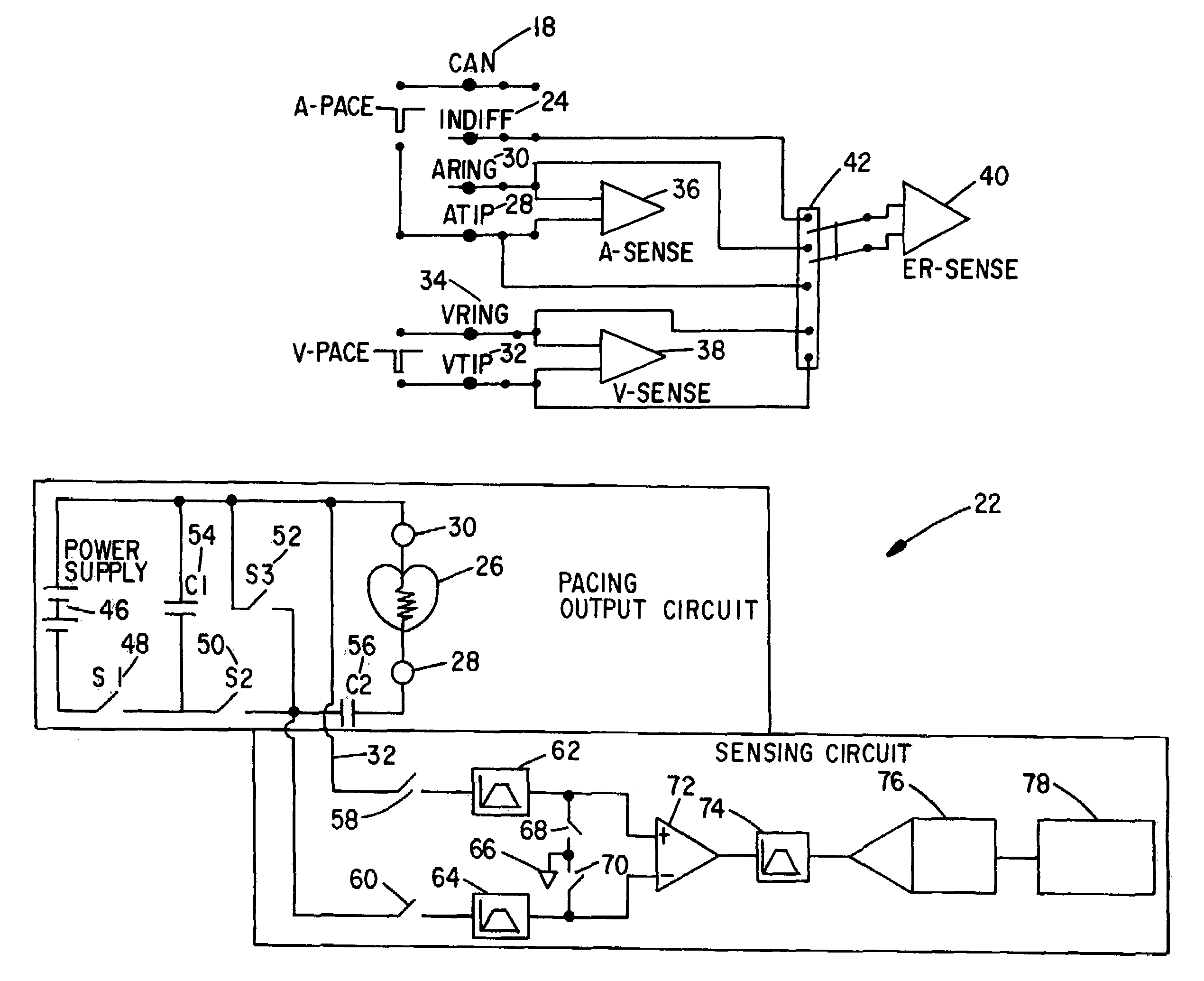
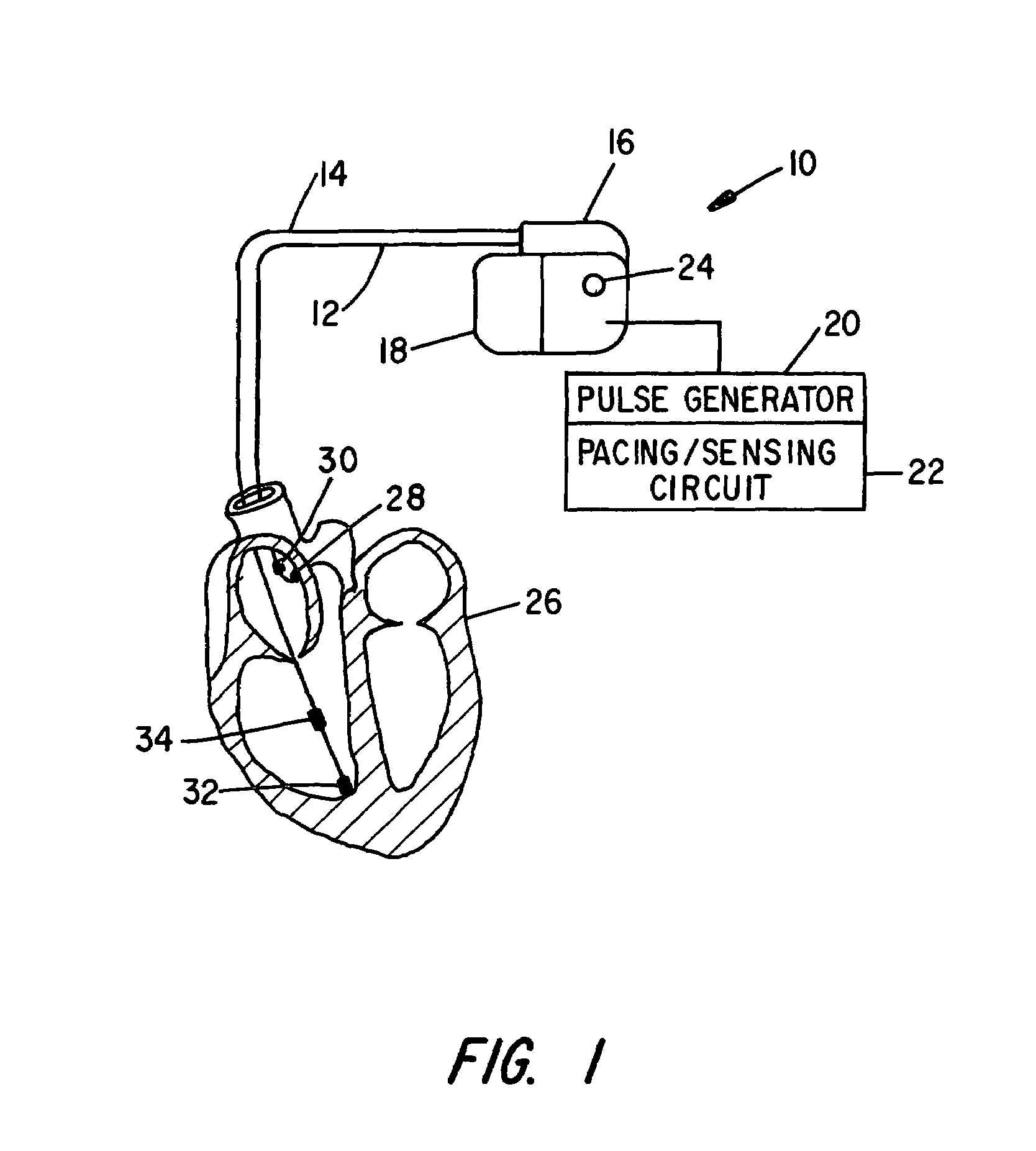
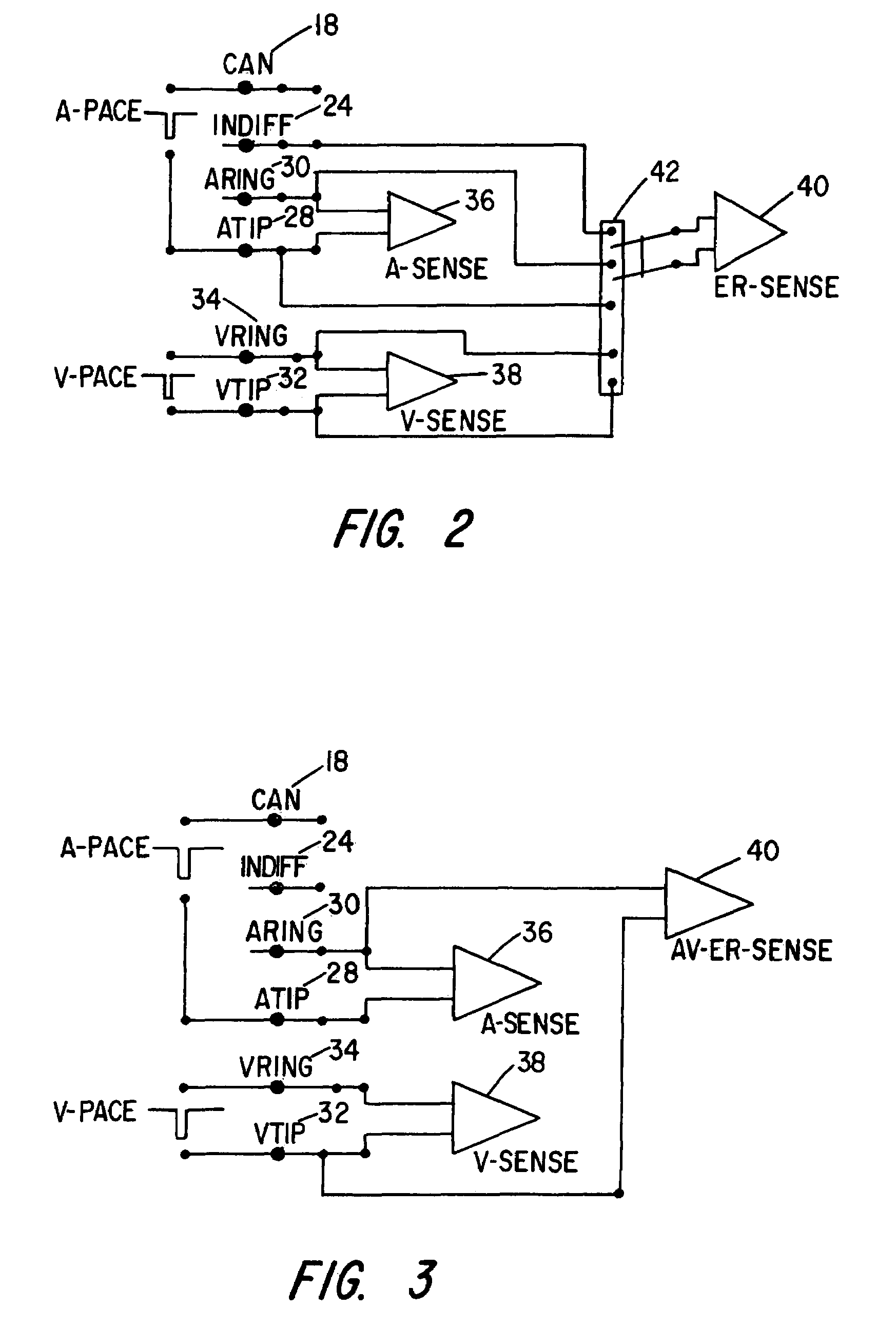
[0041]Referring first to FIG. 1, the cardiac pacing system of the present invention is shown generally and includes a cardiac pacer 10, atrial lead 12 and ventricular lead 14. The cardiac pacer 10 includes a header 16 and can 18, wherein a pulse generator 20 including pacing and sensing circuits 22 are contained therein. An indifferent electrode 24 of suitable known construction is positioned on the can 18 such that the indifferent electrode 24 is electrically isolated from the can 18 and is electrically coupled to the sensing circuit 22. Atrial lead 12 and ventricular lead 14 are engaged to header 16 and may be electrically coupled to the pulse generator 20 and pacing and sensing circuits 22 in a known suitable fashion. The atrial lead 12 is positioned in the atrium of the heart 26, wherein the atrial lead 12 includes a tip electrode 28 and ring electrode 30. The ventricular lead 14 is positioned within the ventricle of the heart 26, wherein the ventricular lead 14 includes a tip e...


PUM


Abstract

A cardiac pacing system that enhances the ability of a cardiac pacer to automatically detect whether a pacing stimulus results in heart capture or contraction. The cardiac pacing system includes a pacing circuit that attenuates polarization voltages or “afterpotential” which develop at the heart tissue / electrode interface following the delivery of a stimulus to the heart tissue, which thereby allows the pacing electrodes to be utilized to sense an evoked response to the pacing stimulus. The cardiac pacing system utilizes the pacing electrodes to sense an evoked response, thereby eliminating the necessity for an indifferent electrode to sense an evoked response. The present invention allows accurate detection of an evoked response of the heart, to thereby determine whether each pacing stimulus results in capture.

Description

BACKGROUND OF THE INVENTION[0001]I. Field of the Invention[0002]The present invention relates generally to the field of cardiac rhythm management devices, including atrial, ventricular, and dual chamber pacemakers. More specifically, the present invention relates to a cardiac pacing system that improves the ability to automatically detect whether a pacing stimulus results in heart capture or contraction. The cardiac pacing system includes a pacing / sensing circuit that attenuates polarization voltages or “afterpotentials” which develop at the heart tissue / electrode interface following the delivery of a stimulus to the heart tissue. The pacing / sensing circuit of the present invention may utilize the pacing electrodes to sense a response evoked by the pacing stimulus. Thus, the present invention allows accurate detection of an evoked response of the heart, to thereby determine whether each pacing stimulus results in capture.[0003]II. Discussion of the Prior Art[0004]Cardiac pacers have...

Claims


Application Information

Patent Timeline
IPC IPC(8): A61N1/362A61N1/37
CPCA61N1/3704A61N1/3716
Inventor ZHANG, GENGKIM, JUNGKUKZHU, QINGSHENG
Owner CARDIAC PACEMAKERS INC
Learn More