
Spinal osteosynthesis assembly comprising the head of an anchoring member and a tool for fixing said head

a technology for bones and joints, applied in the field of spine bones and joints, can solve the problems of most such tools not giving satisfaction, and the tools not giving satisfaction

Inactive Publication Date: 2006-08-15
STRYKER EURO OPERATIONS HLDG LLC
View PDF18 Cites 147 Cited by
  • Summary
  • Abstract
  • Description
  • Claims
  • Application Information

AI Technical Summary

Benefits of technology

[0004]An object of the invention is to provide a tool enabling the head of an anchor member that includes at least one branch to be held appropriately even while said member is being fixed to other parts of the assembly.
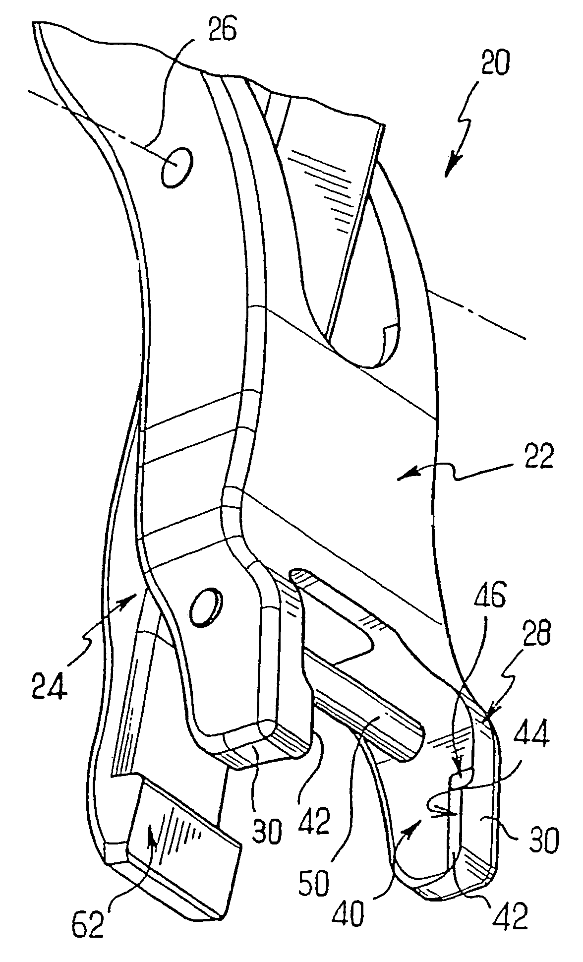
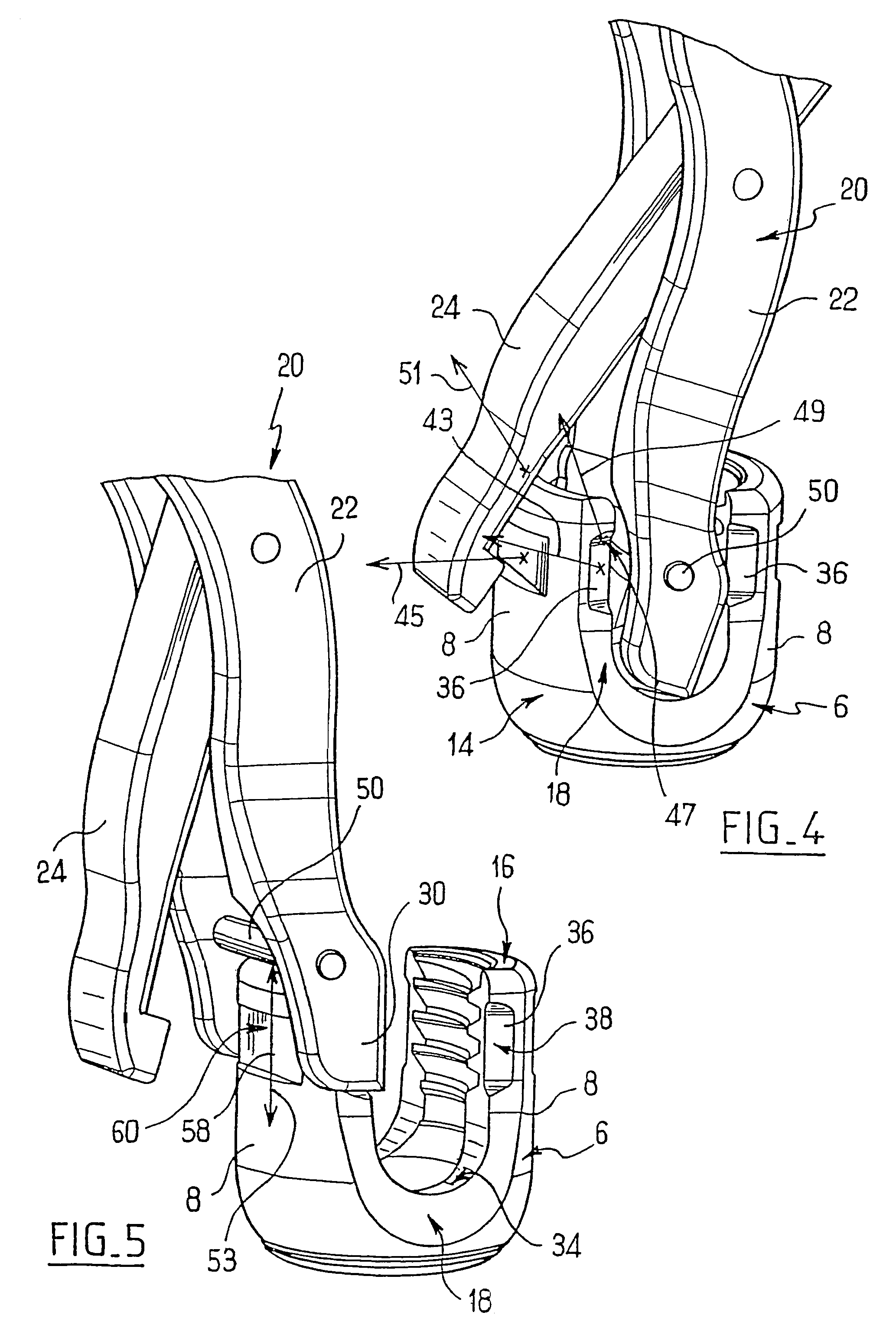
[0009]Thus, the thrust of at least one of the lateral edges makes it possible to apply the additional thrust other than on the face of the branch that is to come into contact with the link element. The additional thrust may, for example, be applied to the tip of the branch or to the other face of the branch. The head can thus be assembled to other elements of the assembly while it is being held by the tool. In addition, the tool presents two or three thrust points on the head, thereby ensuring that the head is held properly by the tool.
[0013]the tool and the lateral edges are shaped with complementary shapes to prevent the tool sliding upwards and / or downwards relative to the head.
[0024]the tool and the face are shaped with complementary shapes to prevent the tool sliding upwards or downwards relative to the head;

Problems solved by technology

Nevertheless, most such tools do not give satisfaction, either because they do not hold the member in satisfactory manner or because their size makes it necessary to release the member in order to be able to fix it to the other elements of the assembly.
In particular, such tools do not give satisfaction when it is necessary to hold an anchor member whose head includes at least one branch.

Method used


Image

  • Spinal osteosynthesis assembly comprising the head of an anchoring member and a tool for fixing said head
  • Spinal osteosynthesis assembly comprising the head of an anchoring member and a tool for fixing said head
  • Spinal osteosynthesis assembly comprising the head of an anchoring member and a tool for fixing said head

Examples


Embodiment Construction

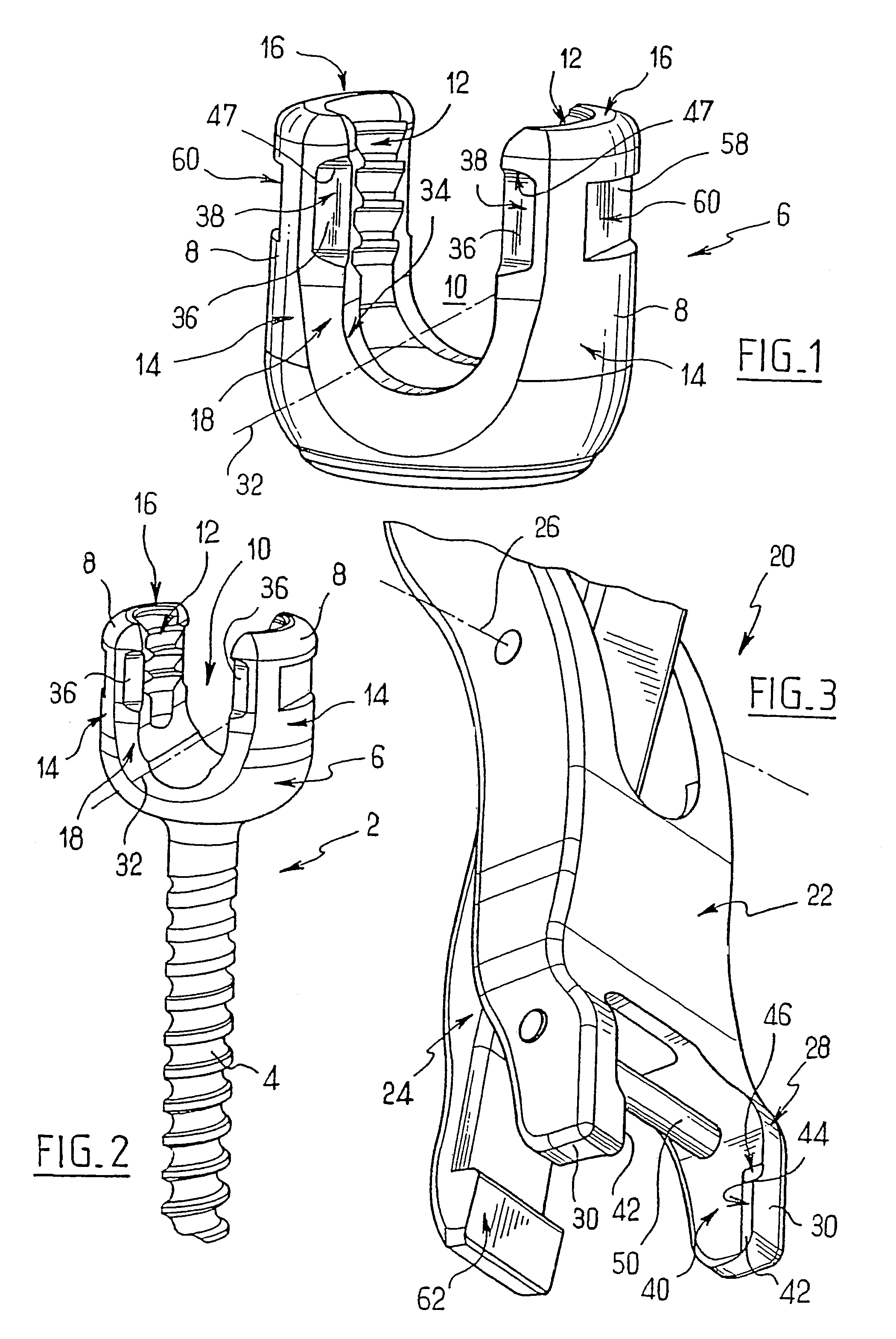
[0038]A preferred embodiment of the system for osteosynthesis of the spine is described below. This system comprises a tool as shown in FIG. 3 and an assembly for osteosynthesis of the spine. The assembly comprises various parts, including mutually identical anchor members of the type shown in FIGS. 1 and 2.

[0039]Each anchor member comprises a threaded shank and a head. In the embodiment of FIG. 1, the head forms a part of an anchor member of conventional polyaxial type. In such a member, the head 6 can be mounted on the shank of the body so as to occupy different angular positions relative thereto and it can be locked in a selected angular position. The head 6 has two branches 8 extending at a distance from each other and facing each other. The two branches give the head a U-shape defining between them a slot 10. Overall, the member is in the form of a tuning fork identical to the variant shown in FIG. 2. The two branches 8 are in the form of cylindrical sectors geometrically defin...


PUM


Abstract

This invention relates to a spinal osteosynthesis assembly comprising the head of an anchoring member consisting of at least one arm and a tool for fixing said head to a spinal osteosynthesis system. The inventive assembly is characterized in that the tool can hold the head by creating at least one lateral support on at least one lateral edge of the arm and an additional support on the head in the opposite direction of the lateral support.

Description

BACKGROUND OF THE INVENTION[0001]The invention relates to assemblies for osteosynthesis of the spine, and in particular to the tools used while fixing such assemblies.[0002]Numerous assemblies are known for the osteosynthesis of the spine, for example the assembly disclosed in document EP-0885 598. Such assemblies generally include anchor members in the form of screws or hooks that are connected to one another by one or more link elements in the form of rods or plates. The function of such assemblies is to rectify the shape of a deformed vertebral column or to enable osteosynthesis to take place in one or more fractured vertebrae. For this purpose, the anchor members are fixed rigidly to the vertebrae.[0003]Each such member must be placed in a very precise position. For this purpose, tools are known that enable the member to be held temporarily so as to assemble it rigidly to the other parts in a desired position. Nevertheless, most such tools do not give satisfaction, either becaus...

Claims


Application Information

Patent Timeline
Patent Type & Authority Patents(United States)
IPC IPC(8): A61B17/58A61F2/00A61B17/70A61B17/88
CPCA61B17/7032A61B17/7076A61B17/7037
Inventor SAINT-MARTIN, PIERRE HENRIVIENNEY, CECILEDE CONINCK, CEDRIC
Owner STRYKER EURO OPERATIONS HLDG LLC
Learn More