
Socket adaptor insertion-removal tool

a socket adaptor and tool technology, applied in the direction of electrical apparatus, electrical discharge tubes, coupling device connections, etc., can solve the problems of repeating the whole process in reverse, difficult to insert the average sized hand down there to install the plug adaptor, and becoming difficult to remove the plug from the lighting string and plug, etc., to achieve the effect of easy insertion and removal of the electrical socket adaptor and easy removal of the adaptor

Inactive Publication Date: 2006-08-15
MAZUR ROBERT
View PDF26 Cites 2 Cited by
  • Summary
  • Abstract
  • Description
  • Claims
  • Application Information

AI Technical Summary

Benefits of technology

[0006]The invention is a socket adaptor insertion-removal tool, comprising: a handle having a top and a bottom; the handle bottom having a shank with an upper end and a lower end; the lower end of the shank formed with a head having at least two conducting prongs wired to a receptacle in the handle top, for insertion into a socket adaptor, wherein the socket adaptor insertion-removal tool can be employed to easily insert and remove an electrical socket adaptor into and out of a socket. When the socket adaptor is inserted with the tool, the tool becomes an adaptor extender, due to the fact that the conducting prongs are wired to a receptacle in the top of the tool handle. Thus, for example, a light bulb socket in a fixture which is recessed in a cavity is converted into a socket that can receive a multi pronged electrical plug, the plug connection being extended into the top of the tool handle to provide an easy access plug receptacle away from the fixture cavity. By a reverse procedure, the tool can later be used to easily remove the adaptor from the fixture.

Problems solved by technology

Outdoor lighting fixtures frequently have a narrow convex shape, which means that it is difficult to place the average sized hand down in there to install the plug adaptor.
Once the adaptor is installed, it again becomes difficult to take the plug from the lighting string and plug it into the adaptor which is now in a tight spot.
Upon time to remove the lighting string, the whole difficult process repeats itself in reverse.
The consequences of the entire procedure may be as severe as a scraped or bruised hand, but the consequences are always a degree of frustration by not being able to easily insert and remove the plug adaptor.

Method used


Image

  • Socket adaptor insertion-removal tool
  • Socket adaptor insertion-removal tool
  • Socket adaptor insertion-removal tool

Examples


Embodiment Construction

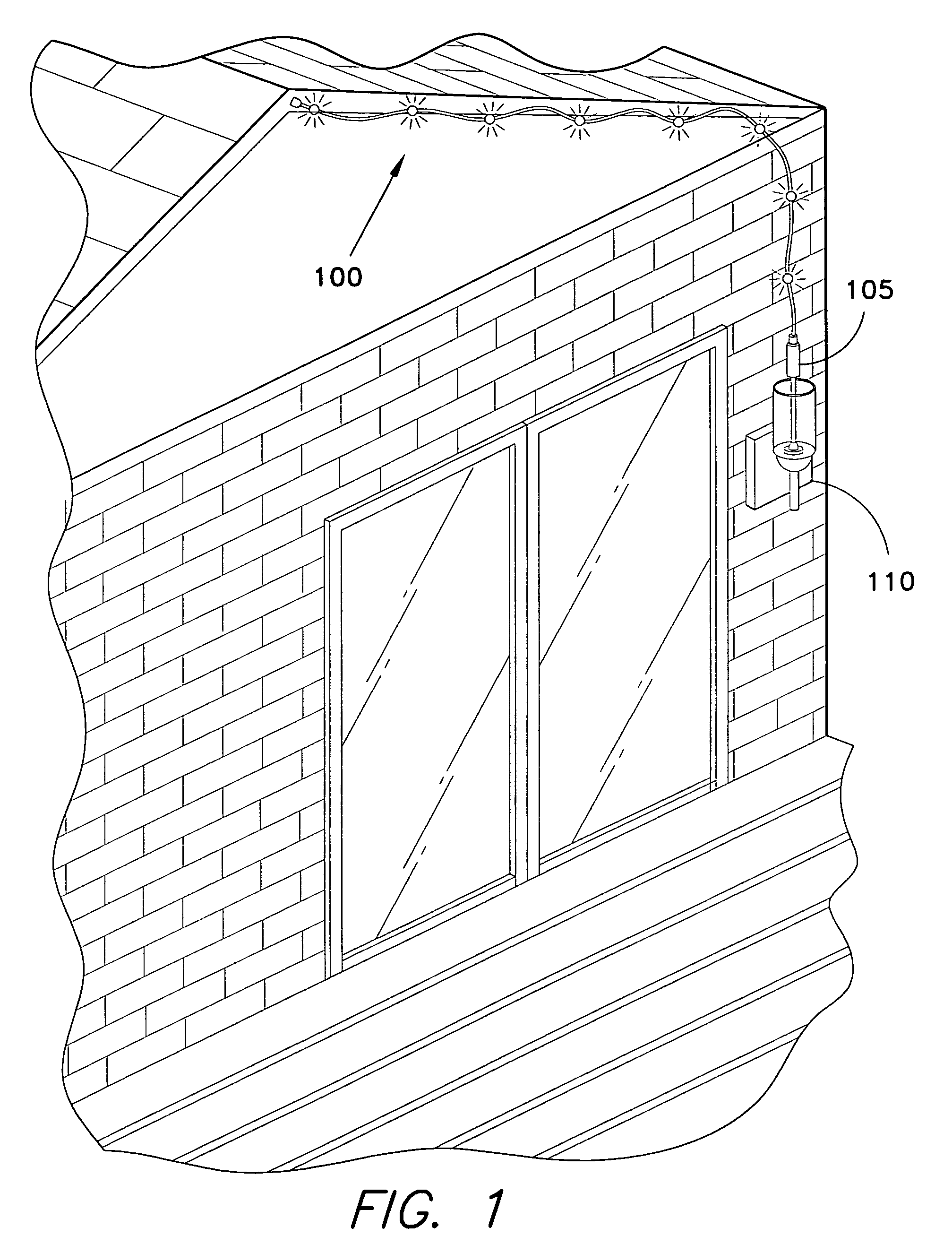
[0012]As can be seen in FIG. 1, the tool 105 of the instant invention is a plugged into a fixture 110, and powers lights in a string 100, th lights being strung out along the roof edge of a home. This illustration simply shows just one of many ways the invention may be employed.

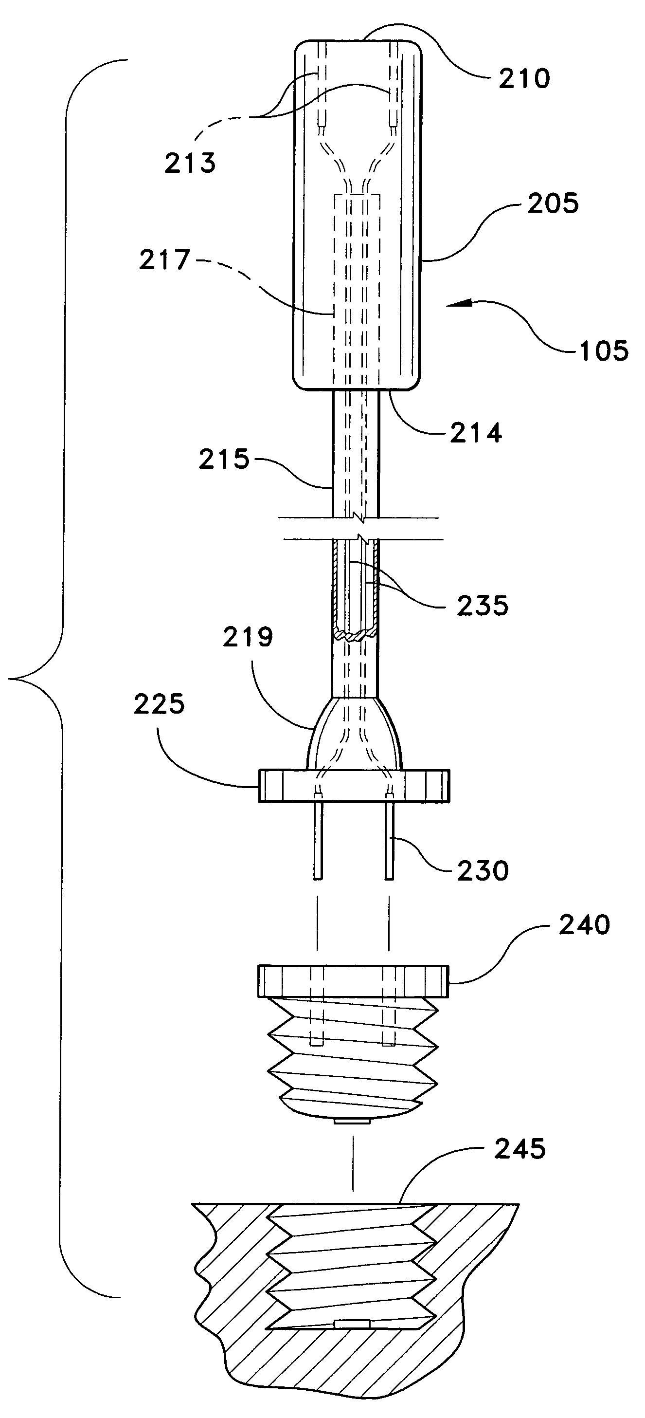
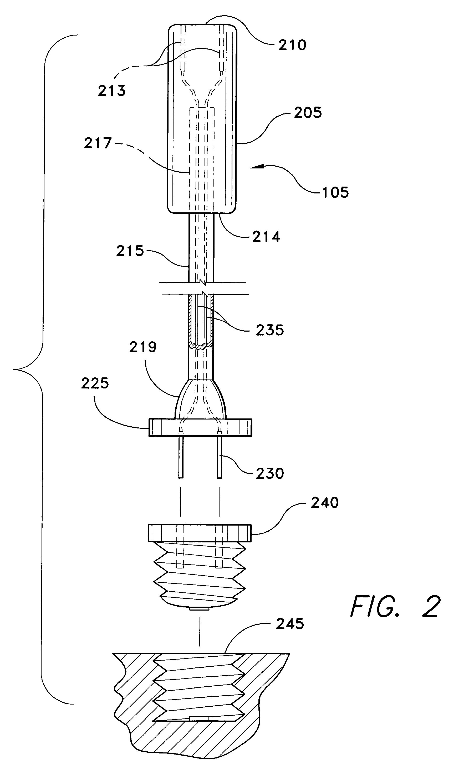
[0013]The socket adaptor insertion-removal tool 105 includes a handle 205 with a top 210 and a bottom 214. The handle bottom 214 has a depending shank 215 with an upper end 217 and a lower end 219. The lower end 219 of the shank 215 has a head 225 with at least two conducting prongs 230 for insertion into a socket adaptor 240. The electrically conducting prongs 230 are wired with electrically conducting wires 235 connecting to a receptacle 213 in the top 210 of the handle 205, so that the socket adaptor insertion-removal tool 105 functions as an adaptor extender, providing electrical power from the receptacle in the top of the handle 213 upon insertion of the socket adaptor 240 into an electrical socket 245 b...


PUM


Abstract

The socket adaptor insertion-removal tool including a handle, a depending shank terminating in a head with at least two conducting prongs wired to a receptacle in the handle top, for insertion into a socket adaptor, thus to provide electrical power from the receptacle in the top of the handle upon insertion of the socket adaptor into an electrical socket. In another embodiment, the handle top end does not have a receptacle.

Description

BACKGROUND OF THE INVENTION[0001]1. Field of the Invention[0002]The present invention relates to a tool for insertion and removal of electrical socket adaptors.[0003]2. Description of the Related Art[0004]Often times consumers attempt to install or remove electrical socket adaptors from very tight spots, not easily reached by hand. One common example is the insertion of adaptors for use with holiday lighting strings. Usually consumers attempt to install these lights using an outdoor lighting fixture as a power source. Outdoor lighting fixtures frequently have a narrow convex shape, which means that it is difficult to place the average sized hand down in there to install the plug adaptor. Once the adaptor is installed, it again becomes difficult to take the plug from the lighting string and plug it into the adaptor which is now in a tight spot. Upon time to remove the lighting string, the whole difficult process repeats itself in reverse. The consequences of the entire procedure may ...

Claims


Application Information

Patent Timeline
IPC IPC(8): H01R25/00
CPCH01R33/94
Inventor MAZUR, ROBERT
Owner MAZUR ROBERT
Learn More