
Dual magnification folding travel mirror with annular illuminator

a travel mirror and annular illuminator technology, applied in the field of mirrors, can solve the problems of not providing magnified images, affecting the quality of travel mirrors, and the optimal arrangement of lighting and seating near the suitable mirror, etc., and achieves the effect of convenient use, convenient use and small siz

Active Publication Date: 2006-08-15
ZADRO INC
View PDF4 Cites 77 Cited by
  • Summary
  • Abstract
  • Description
  • Claims
  • Application Information

AI Technical Summary

Benefits of technology

[0007]An object of the present invention is to provide a portable illuminated, dual magnification mirror device which is sufficiently small and light in weight to be conveniently and safely transportable in a traveler's luggage, carry-on bag, purse or briefcase.
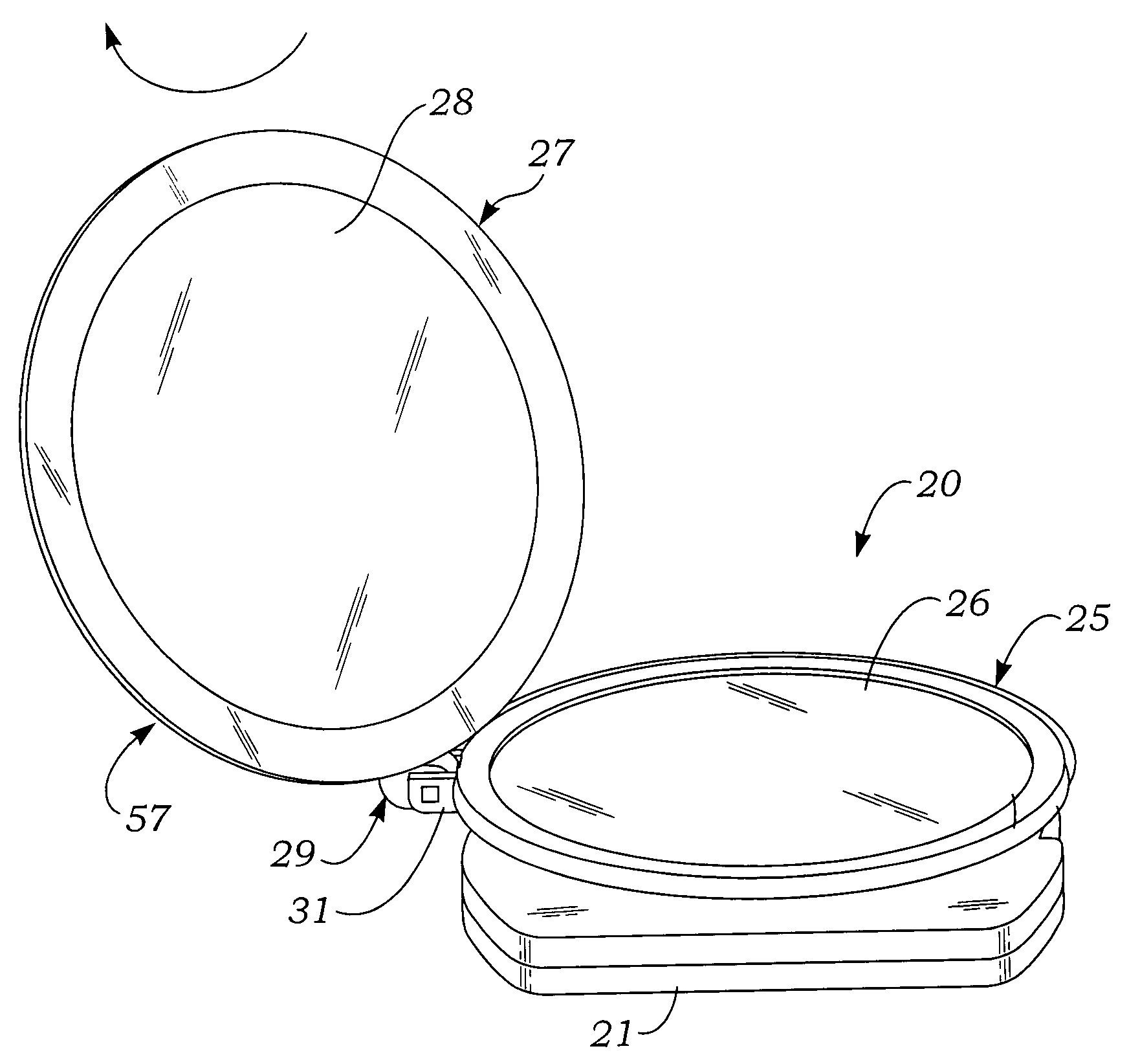
[0010]Another object of the invention is to provide an illuminated travel mirror which includes a primary mirror mounted in a primary frame provided with a peripheral annular illuminator, a secondary mirror mounted in a secondary frame which has a peripheral light-transmissive annular ring-shaped bezel, and a hinge coupler provided with a pivotable joint which connects peripheral edges of the primary and secondary frames and which enables the secondary mirror to be pivoted to a position overlying the main mirror frame, enabling light from the illuminator of the primary mirror frame to be transmitted through the light transmissive bezel of the secondary mirror and thereby illuminate an object field in front of the secondary mirror.
[0014]Briefly stated, the present invention comprehends a portable travel mirror device which includes a pair of mirrors having different magnification factors, e.g., 1× and 5×, and an annular illumination source which is effective in selectably illuminating object fields of both mirrors.

Problems solved by technology

However, lodgings at travel destinations usually do not have the optimal arrangements of lighting and seating located near a suitable mirror, such as one has available at his or her personal residence.
But most travel lodgings have at best 1× flat mirrors which do not provide magnified images.

Method used


Image

  • Dual magnification folding travel mirror with annular illuminator
  • Dual magnification folding travel mirror with annular illuminator
  • Dual magnification folding travel mirror with annular illuminator

Examples


Embodiment Construction

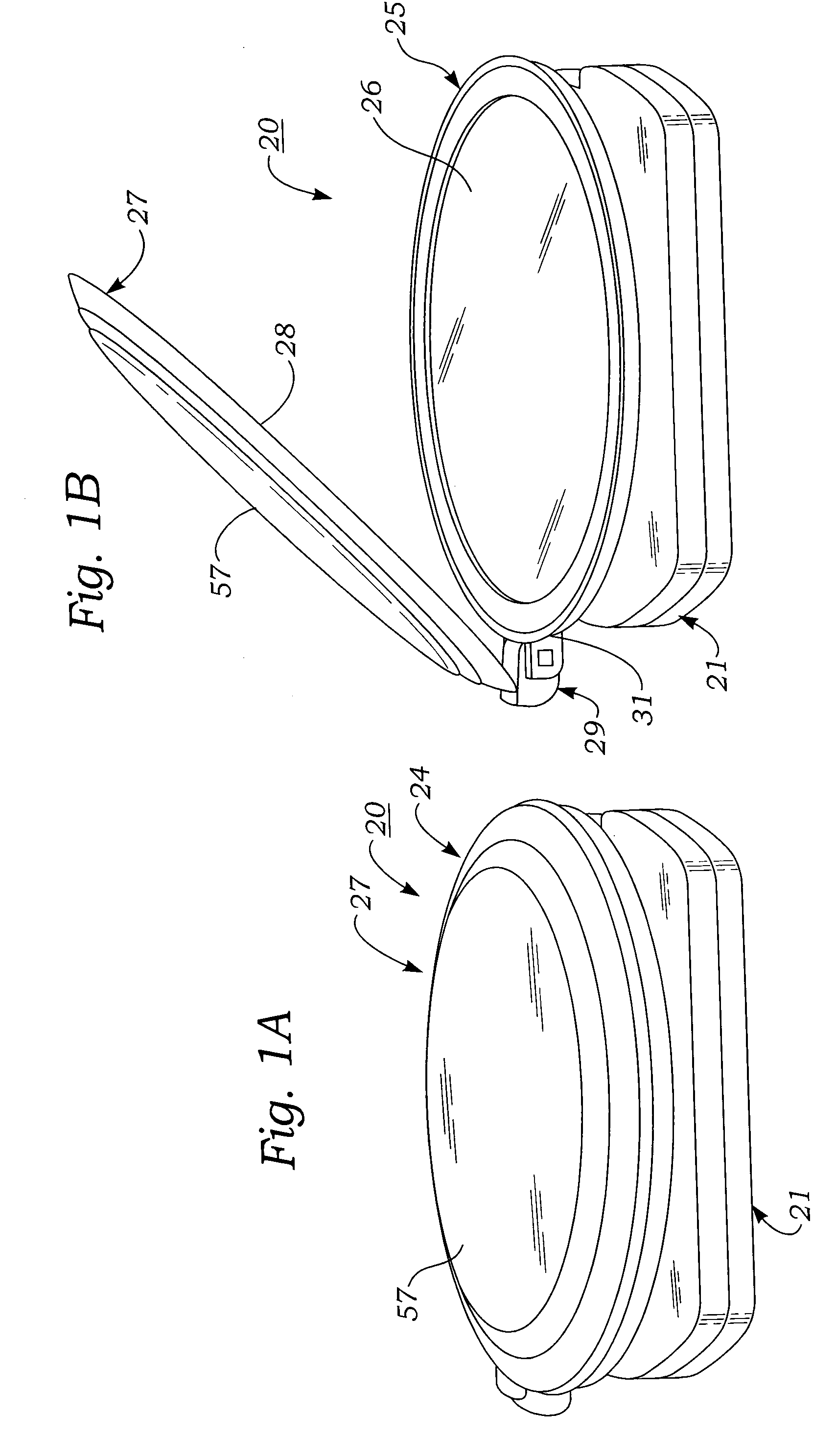
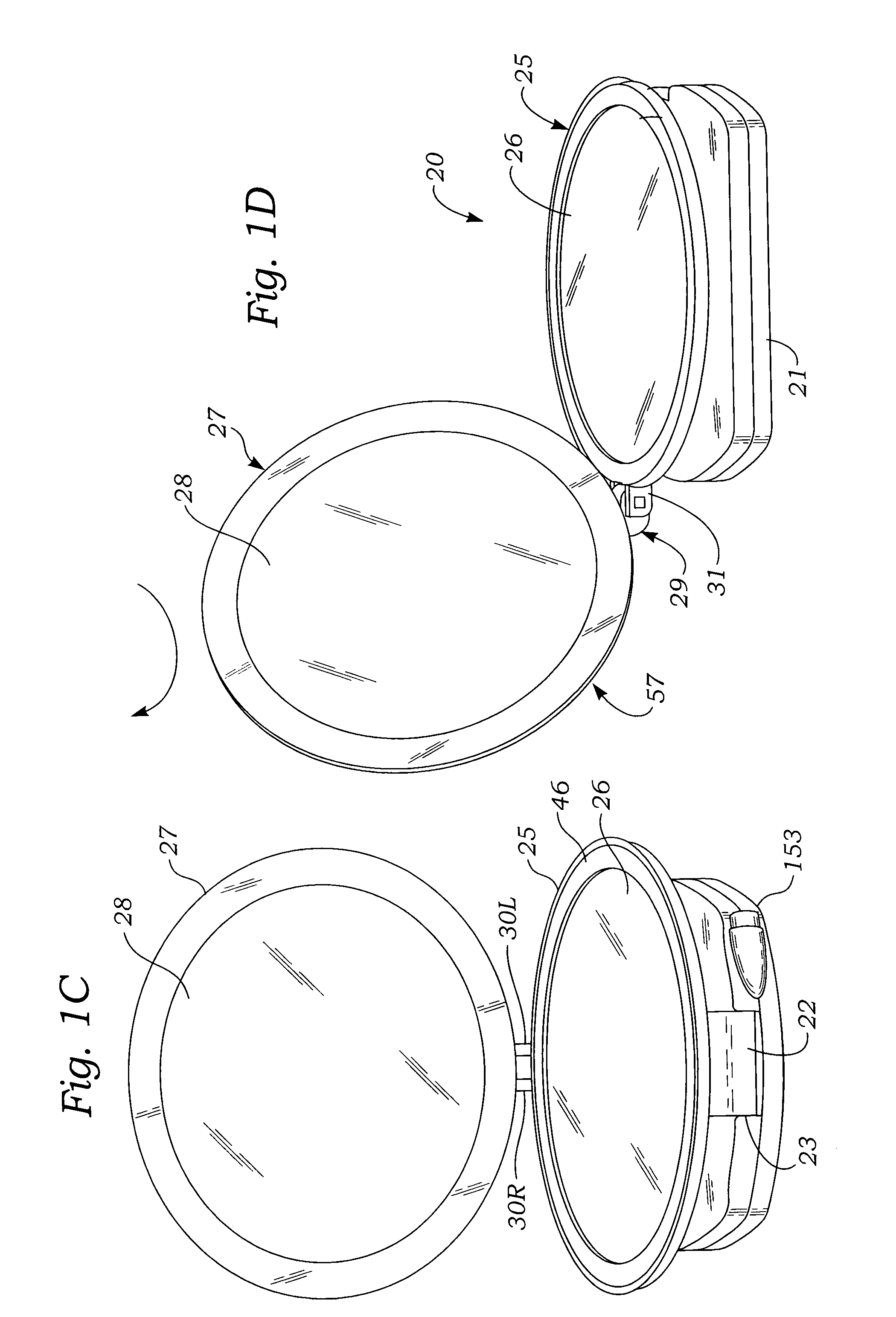
[0076]FIGS. 1A–21 illustrate various aspects of a dual magnification folding travel mirror with annular illuminator according to the present invention.

[0077]Referring first to FIGS. 1A–8A, it may be seen that a dual magnification travel mirror with annular illuminator 20 according to the present invention includes a base 21, an elongated, generally rectangularly-shaped handle 22 pivotably mounted at a lower end thereof to a front edge of the base by a handle pivot joint 23, and a dual mirror assembly 24 telescopically mounted to an upper end of the handle.

[0078]As shown in FIGS. 6A–9, dual mirror assembly 24 includes a first, lower, or primary circular dish-shaped mirror frame 25 in which is mounted a first, lower or primary circular disk-shaped mirror 26. As is also shown in those figures, dual mirror assembly 24 includes a second, upper or secondary circular plate-shaped mirror frame 27 in which is mounted a second, upper or secondary circular disk-shaped secondary mirror 28. As s...


PUM


Abstract

A portable travel mirror device includes a base, a handle pivotably mounted to the base, and a dual mirror assembly mounted to the handle which is pivotable and telescopically extendable between compact transport and upright use configurations, and includes a circular primary mirror frame holding a magnifying mirror encircled by a ring-shaped lamp energized by a power source within the base, and overlain by a diffuser ring. A secondary mirror pivotably and swivelably attached to the primary mirror frame has a different magnification factor, e.g., 1×, and is pivotable upwards from a travel position overlying and protecting the primary mirror to an upright use position, and is also swivelable into contact with the primary mirror frame, whereby light from the lamp is transmitted through the diffuser ring and a transparent secondary mirror bezel to illuminate objects in front of the primary or secondary mirror.

Description

BACKGROUND OF THE INVENTION[0001]A. Field of the Invention[0002]The present invention relates to mirrors of the type used by people to facilitate performance of personal care functions such as shaving, applying cosmetics, and the like. More particularly, the invention relates to a novel travel mirror device which is collapsible into a compact, lightweight, readily transportable assembly, and which includes a pair of mirrors of different relative magnification and an integral annular illuminator which is effective in illuminating objects in front of both mirrors.[0003]B. Description of Background Art[0004]People who travel frequently to distant locations often must deal with the absence of conveniences which are taken for granted in their home environments. For example, women who perform grooming tasks such as applying cosmetics and the like typically perform such tasks at a customary location which is adequately lighted and which is provided with a fixed wall-mounted mirror, or a mi...

Claims


Application Information

Patent Timeline
Patent Type & Authority Patents(United States)
IPC IPC(8): F21V7/18
CPCA45D42/10
Inventor ZADRO, ZLATKO
Owner ZADRO INC
Learn More