
Communication system

a communication system and communication technology, applied in the field of communication systems, can solve the problems of many different plug-in connections, lack of flexibility of interfaces, and inability to meet the needs of users, and achieve the effect of low hardware and software costs

Inactive Publication Date: 2006-08-08
ENTERPRISE SYST TECH S A R L
View PDF18 Cites 5 Cited by
  • Summary
  • Abstract
  • Description
  • Claims
  • Application Information

AI Technical Summary

Benefits of technology

[0015]It is the object of the present invention to indicate a solution by way of a PC and a telephone can be connected with a low hardware and software expense, and in which additional peripheral devices can be connected via the interface between the PC and the telephone.

Problems solved by technology

The Up0 interface, however, is not internationally standardized.
One problem in the contemporary PC world is the lack of flexibility of the interfaces used.
However, to use such peripheral devices it is necessary to open the computer and install additional plug-in cards.
Another disadvantage of the many different interfaces in the PC domain is the use of many different plug connections.
It is disadvantageous, however, that this interface does not have the bandwidth required for complete controlling by the PC.
The connection of further peripheral devices to the interface between the personal computer and the telecommunications terminal device, however, is no more possible than is stand-alone operation of the telecommunications terminal device when the personal computer is turned off.

Method used


Image

  • Communication system
  • Communication system
  • Communication system

Examples


Embodiment Construction

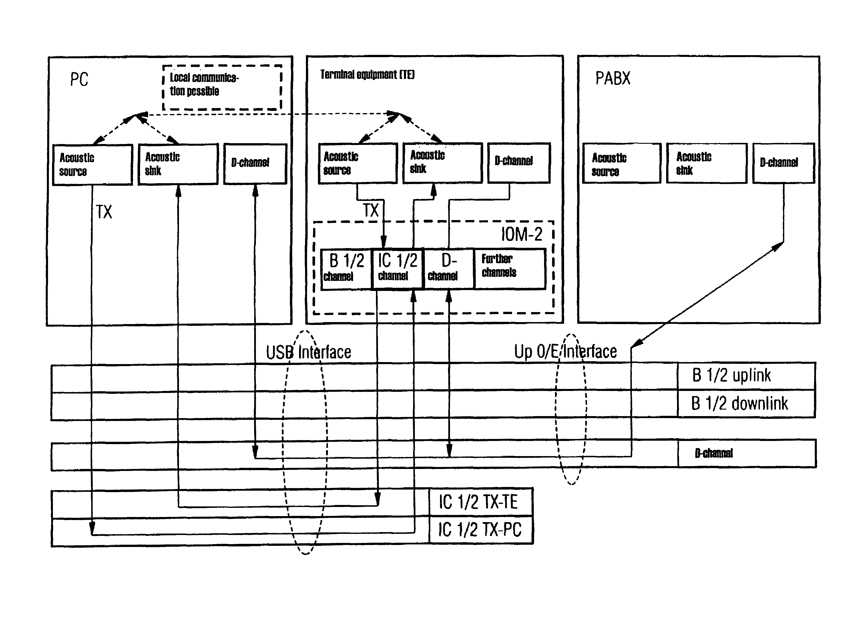
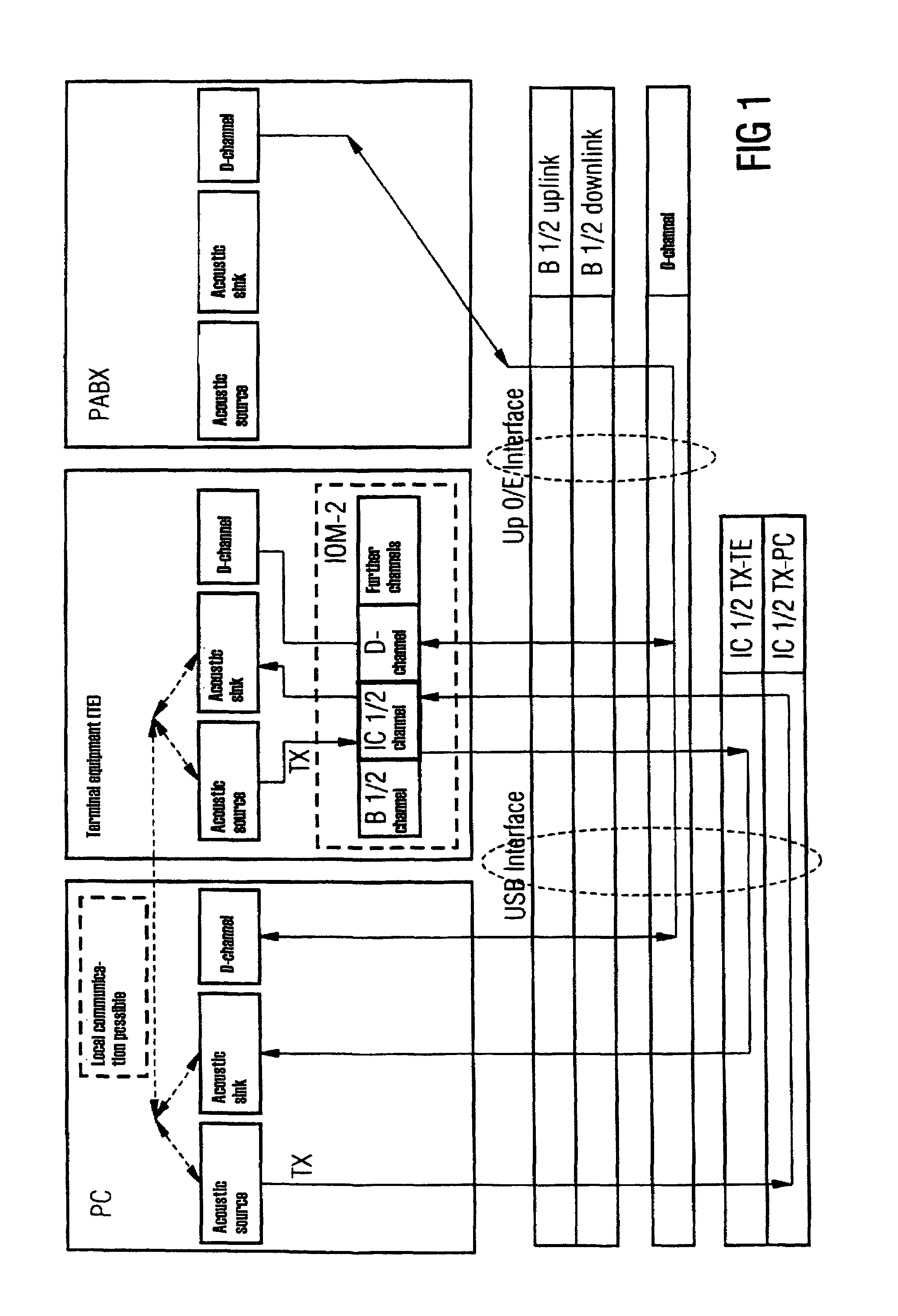
[0028]According to a preferred embodiment of the present invention, shown in FIG. 1, the terminal apparatus (TE), preferably a telephone, is connected physically with a private branch exchange (PABX) via a Up0 / E interface. According to another embodiment, the terminal apparatus can be connected with a public telephone network via another interface, for example an S0 or Uk0 interface. PC and terminal apparatus are connected physically, preferably via a USB bus. In FIG. 5, the cabling between PC, terminal apparatus (TE) and private branch exchange that is required for the exchange of information according to FIG. 1 is shown.

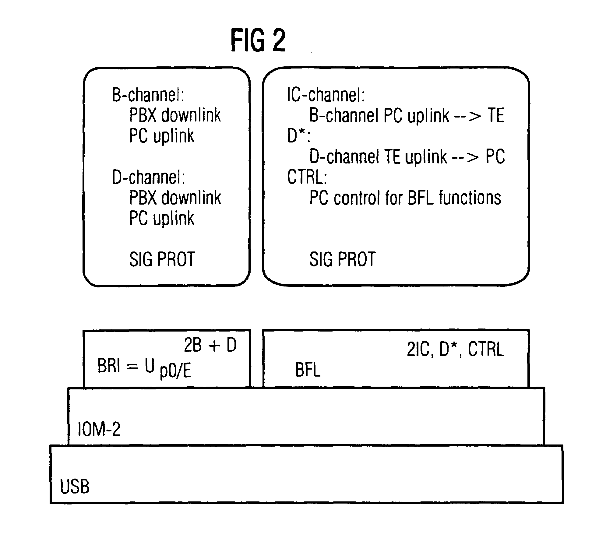
[0029]In principle, all known busses that can transmit a bandwidth of (4×64 Kbit / s+16 Kbit / s) (4 B channels and 1 D channel) are possibilities for the physical connection between PC and terminal apparatus. However, the hardware expense in the terminal apparatus is particularly low if the physical interface between PC and terminal apparatus can accept the entire ban...


PUM


Abstract

A communication system has a computer device, a telecommunication terminal apparatus, and a switch that can be connected to a public telephone network. The computer device and the telecommunication terminal apparatus are connected via a first bus system, and the telecommunication terminal apparatus is connected to the switch via an interface. In a first operating mode of the telecommunication terminal apparatus, data is received from the switch and rerouted to a first bus system and to the computer device. The computer has a processor to process data received by the telecommunication terminal apparatus, and forwards this data to the telecommunication terminal apparatus via the first bus system and the data are further transmitted by the telecommunication terminal apparatus. The first bus system has a greater bandwidth than a second bus system that connects individual internal assemblies of the telecommunication terminal apparatus. In the first operating mode, the telecommunication terminal also forwards data produced by the telecommunication terminal apparatus to the computer device and the computer processor processes the received data. This data is sent back via the first bus system to the telecommunication terminal apparatus which reroutes this data to the switch.

Description

BACKGROUND OF THE INVENTION[0001]1. Field of the Invention[0002]The present invention relates to a communication system for connecting at least one telecommunication terminal apparatus and at least one computer device to a switching device.[0003]2. Description of the Related Art[0004]Analog telephone equipment is increasingly being replaced by digital equipment, based predominantly on the ISDN (Integrated Services Digital Network) standard. ISDN is defined by several international digital communication standards that are recognized worldwide by telephone companies. ISDN technology is used to send both speech and data that can include graphics, sound, films and digital signals via public telephone networks. The ISDN standard comprises digital standard transmission protocols, terminals and connection cables. The user is provided with two types of ISDN terminals. The international base terminal (S0) comprises two B channels, each having 64 Kbit / s, and a D channel having 16 Kbit / s. The ...

Claims


Application Information

Patent Timeline
Patent Type & Authority Patents(United States)
IPC IPC(8): H04L12/50H04M3/42H04Q3/62H04Q11/04
CPCH04M3/42323H04M7/0015H04Q11/0471H04Q2213/13292H04Q2213/13176H04Q2213/13209H04Q2213/1322H04Q2213/13093
Inventor BRIESKORN, JURGEN
Owner ENTERPRISE SYST TECH S A R L
Learn More