Multiplexer and demultiplexer
- Summary
- Abstract
- Description
- Claims
- Application Information
AI Technical Summary
Benefits of technology
Problems solved by technology
Method used
Image
Examples
Example
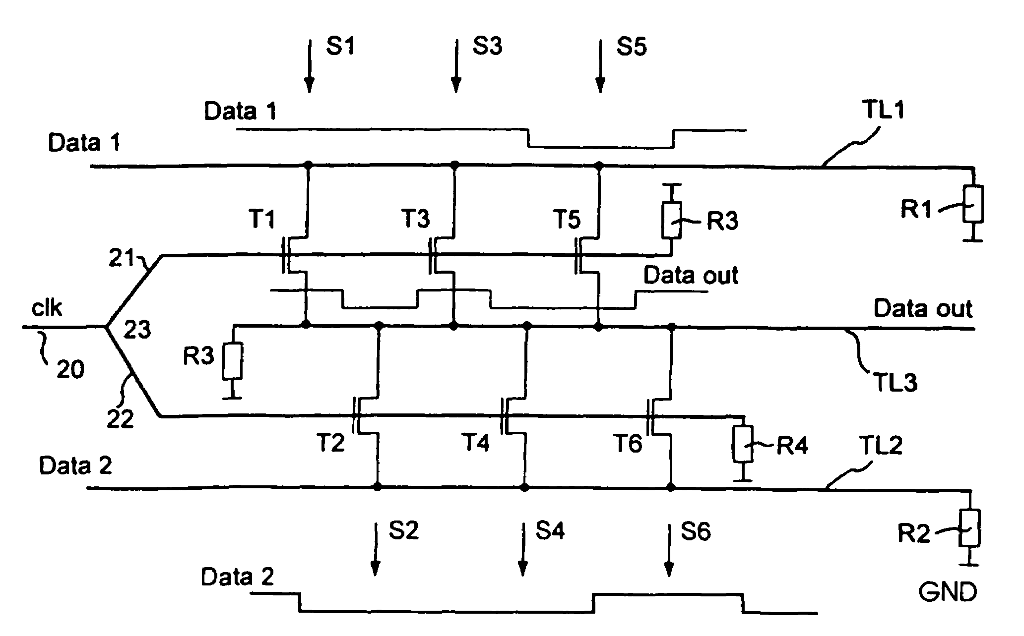
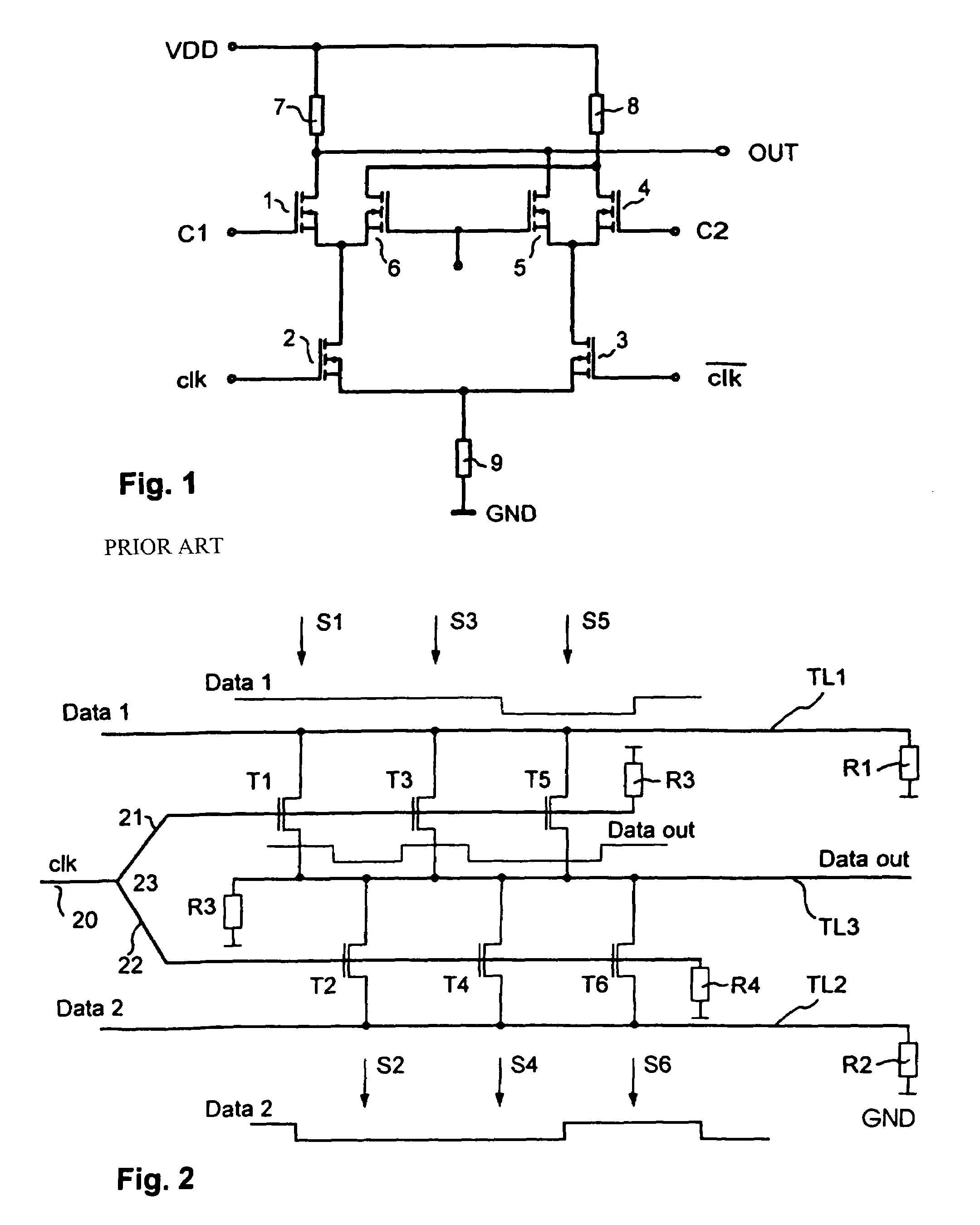
[0039]In FIG. 2 a simplified block diagram of a first embodiment of a distributed multiplexer according to the invention is depicted, which represents a 2 to 1 multiplexer. At the inputs of the multiplexer input signals Data 1 and Data 2 and a control signal in form of a clock signal clk are applied. The input signals Data 1 and Data 2 form the data streams, which shall be multiplexed and then form an output signal Data out. For this purpose, the multiplexer comprises a first transmission line TL1 which leads the first input signal Data 1 and a second transmission line TL2 which leads the second input signal Data 2. A third transmission line TL3, also called data output line or output transmission line, leads the output signal Data out. These three transmission lines TL1, TL2 and TL3 are phase matched transmission lines. Therefore, the phase velocities on the input and output transmission lines TL1, TL2 and TL3 are equal. Between the first input transmission line TL1 and the output ...
PUM
 Abstract
Description
Claims
Application Information
 - R&D Engineer
- R&D Manager
- IP Professional
- Industry Leading Data Capabilities
- Powerful AI technology
- Patent DNA Extraction
Browse by: Latest US Patents, China's latest patents, Technical Efficacy Thesaurus, Application Domain, Technology Topic, Popular Technical Reports.
© 2024 PatSnap. All rights reserved.Legal|Privacy policy|Modern Slavery Act Transparency Statement|Sitemap|About US| Contact US: help@patsnap.com


