
Commodity display device

a display device and commodity technology, applied in the direction of light support devices, washstand accessories, scaffolding, etc., can solve the problems of static attaching/removing positions of support members, difficult to smoothly and quickly conduct commodity display work, and easy removal of shelf members or hanging members. , to achieve the effect of stably holding the support member and conducting quickly and easily

Inactive Publication Date: 2006-08-08
TAMATOSHI INDSHOKK
View PDF15 Cites 28 Cited by
  • Summary
  • Abstract
  • Description
  • Claims
  • Application Information

AI Technical Summary

Benefits of technology

[0010]The present invention remedies the existing drawbacks and provides a commodity display device which can display or hang commodities with shelf members or hanging members, which are attached to a wall surface member, readily and securely attached by a single operation from below. It is also an advantage of the invention to provide a commodity display device, which can prevent screws for fixing the wall surface member from being exposed on the wall surface.
[0011]A commodity display device according to an embodiment of the present invention comprises a wall surface member having a turning space with catching grooves formed on its inside wall by forming a catching protrusion bar on a long vertical wall surface, which is to be attached to a wall surface or the like of a shop or the like, so to protrude and overhang from the vertical wall surface and extending the catching protrusion bar downward to form a semicircular flection, and a hanging shelf member having a catching member vertically formed at a leading end of a rod shape support member for supporting commodities or the like to be displayed, a leading end of the catching member bent into an L shape to form a standing part, and engagement projections formed on the bent part and the pointed part of the standing part; wherein the standing part of the hanging shelf member is turned along the inside wall surface of the turning space of the wall surface member to engage the engagement projections of the standing part with the catching grooves, the catching member comes into close contact with the vertical wall surface, and the support member becomes substantially vertical with respect to the vertical wall surface.
[0012]The turning space of the wall surface member of the invention comprises a catching groove formed on the vertical wall surface; a catching groove formed on the inner side of the leading end of the semicircularly bent catching protrusion bar; and a hollow part in which the catching member turns.
[0013]The engagement projections of the hanging shelf member are formed by protruding on the back surface of the standing part which is bent into the L shape and slanting a pointed part formed by bending the catching member.
[0014]According to the commodity display device of the invention, the standing part of the catching member of the hanging shelf member is turned to insert from below into the turning space of the wall surface member, and two engagement projections of the standing part are turned within the turning space to be automatically guided so to be fitted into the catching grooves of the turning space. In this case, the catching member comes into close contact with the vertical wall surface, and the engagement projections are fitted into the catching grooves by the own weight of the hanging shelf member. An upward force does not disconnect the fitting of the engagement projections. Thus, the support member can be held stably.
[0015]The commodity display device of the invention has the catching grooves in the hollow part and the engagement projections mutually engaged by the turning operation of the engagement projections and a pressure welding by the own weight of the hanging shelf member.

Problems solved by technology

But, there was a problem that the shelf members or the hanging members were easily removed by applying an upward small force because they were not locked against an upward force.
Work to horizontally fix plural catching members to the wall surface member is troublesome, and it is hard to smoothly and quickly conduct the commodity displaying work.
Therefore, after the catching members are attached, each attaching / removing operation of the hooks or the brackets to those catching members is troublesome, and their attaching / removing positions become static.

Method used


Image

  • Commodity display device
  • Commodity display device
  • Commodity display device

Examples


Embodiment Construction

[0028]One embodiment of the invention will be described with reference to the accompanying drawings.

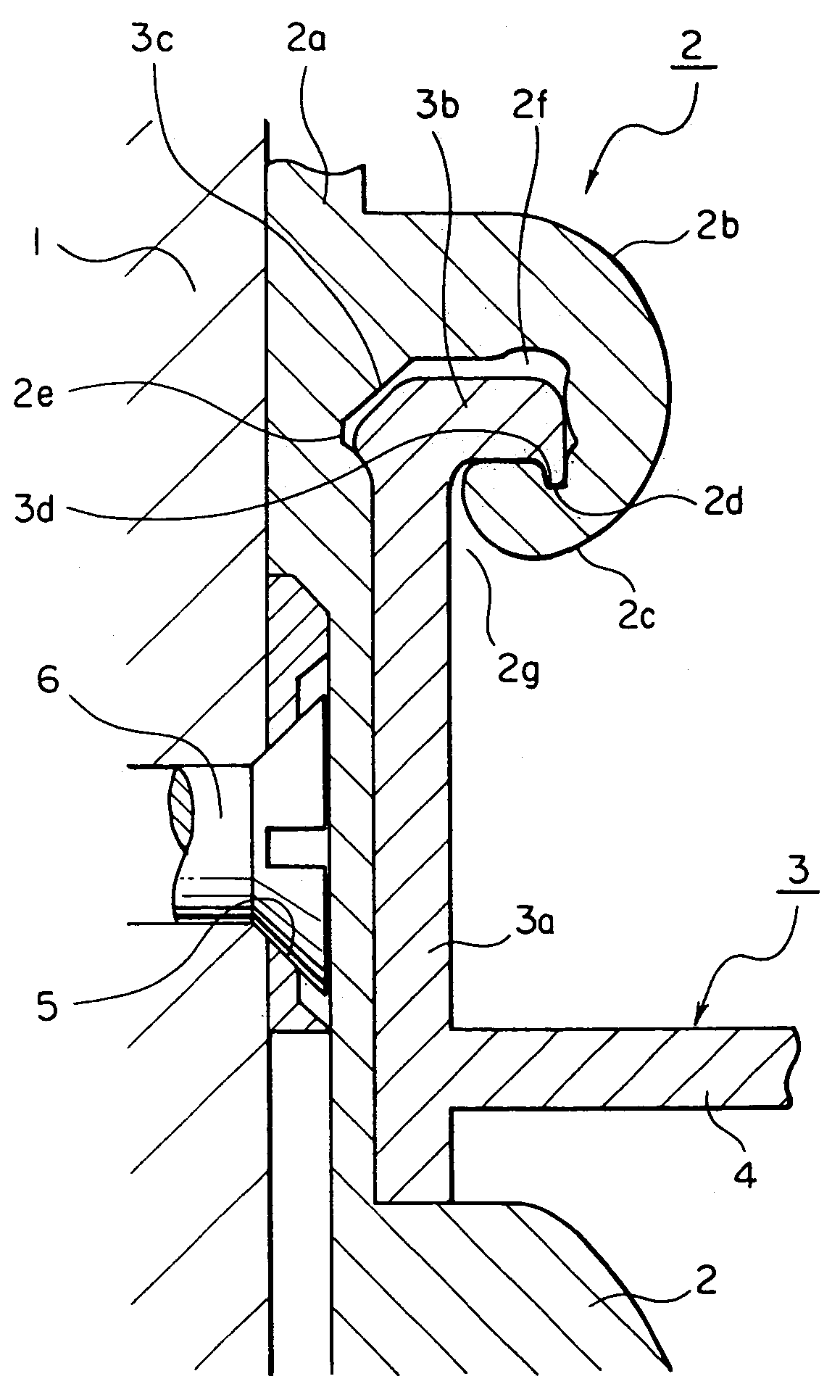
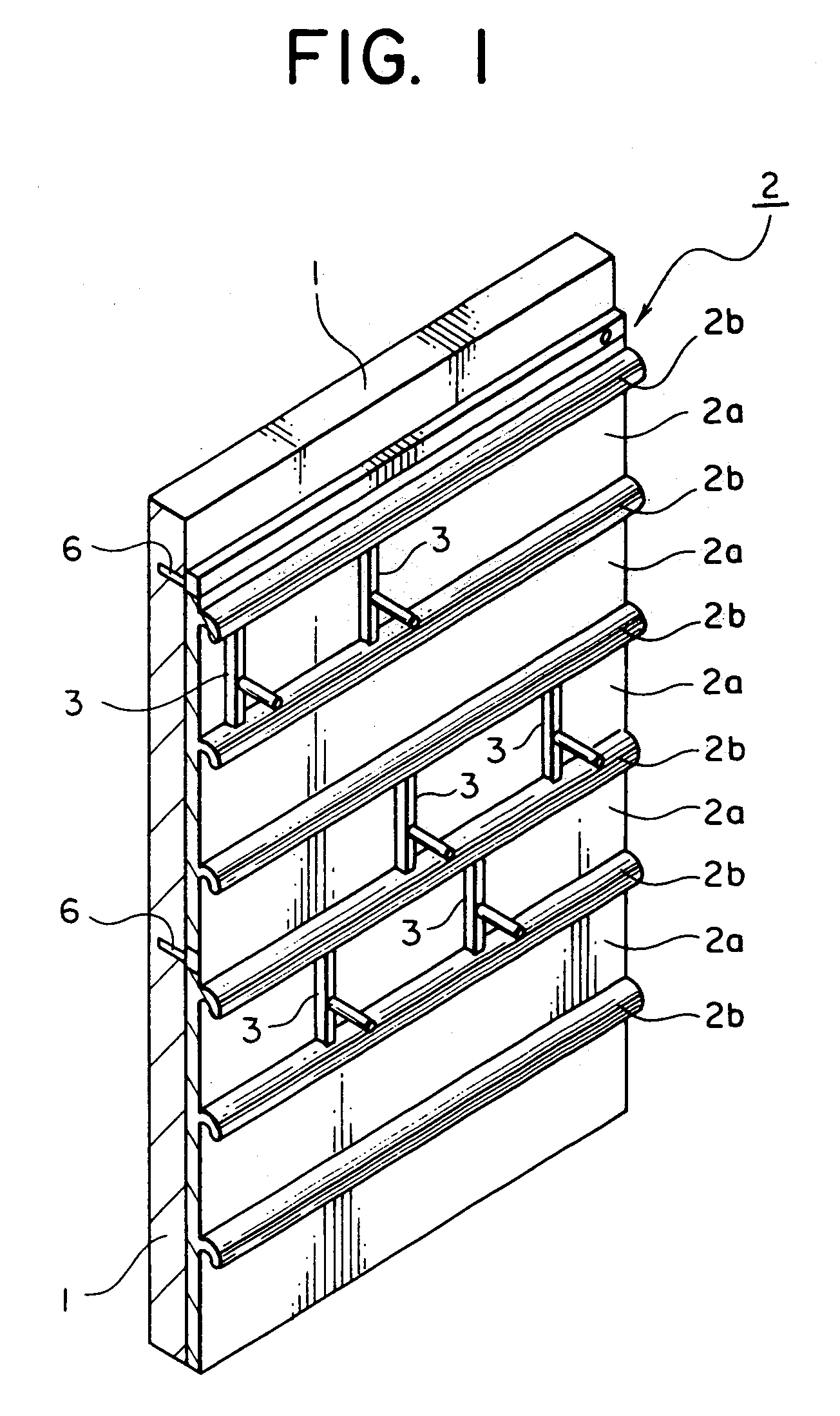
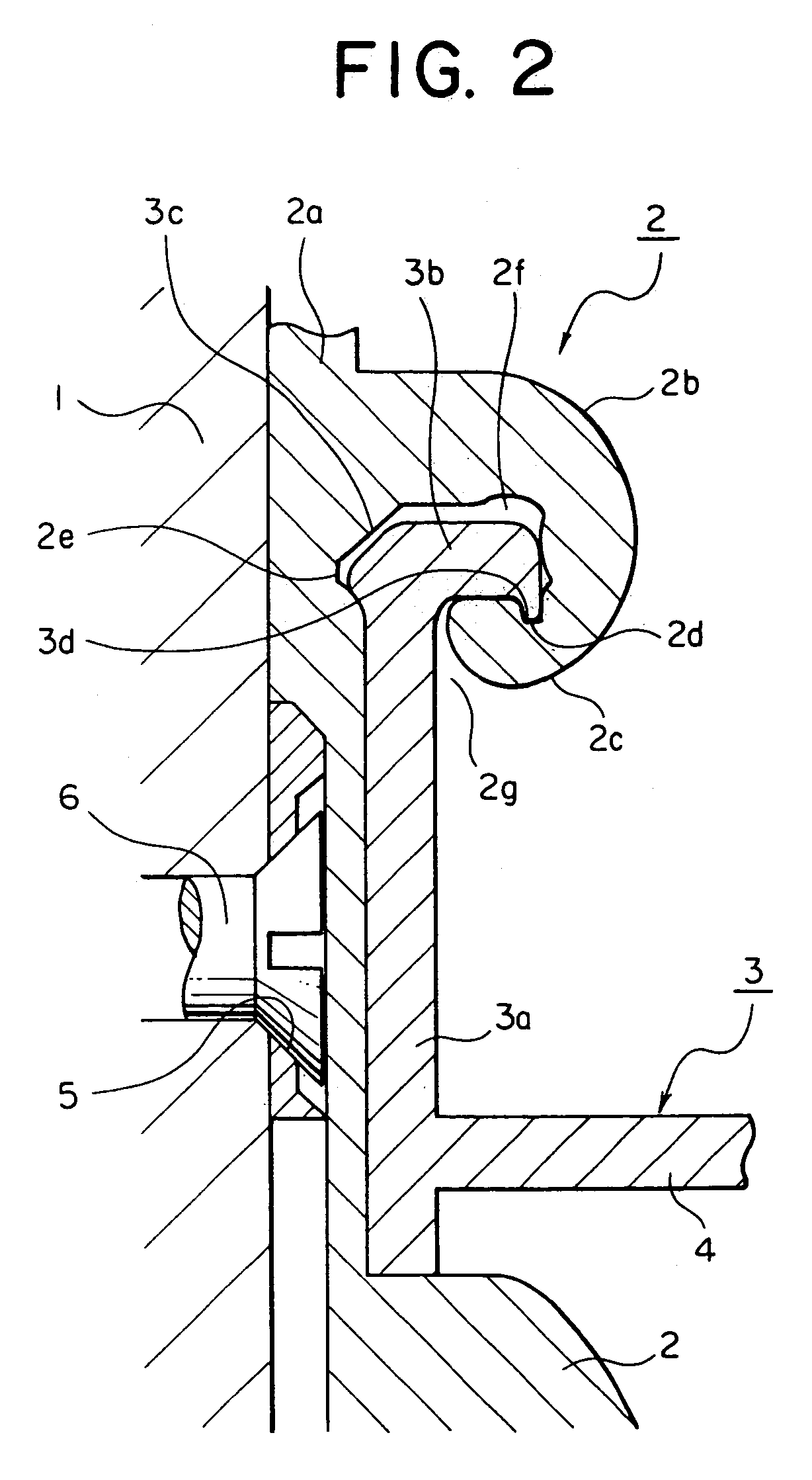
[0029]FIG. 1 is a perspective view schematically showing the commodity display device according to one embodiment of the invention; FIG. 2 is an expanded sectional view of a substantial part of the commodity display device according to an embodiment of the invention; FIG. 3 is an expanded sectional view of a substantial part of the structure of wall surface members attached to a wall surface according to an embodiment of the invention; FIG. 4 is a perspective view showing an example of a hanging shelf member according to an embodiment of the invention; FIG. 5 is an expanded sectional view of a substantial part showing a procedure of assembling the commodity display device according to an embodiment of the invention; FIG. 6 is an expanded sectional view of the substantial part showing the procedure of assembling the commodity display device according to the embodiment of the invention;...


PUM


Abstract

Catching grooves 2d, 2e are formed in a turning space 2f of a catching protrusion bar 2b, engagement projections 3c, 3d are formed on a standing part 3b of a catching member 3a, and the standing part 3b is inserted into the turning space 2f, so that the engagement projections 3c, 3d are respectively engaged with the catching grooves 2d, 2e by the own weight of the catching member 3a.

Description

CROSSREFERENCE TO RELATED APPLICATIONS[0001]This application is based upon and claims the benefit of priority from the prior Japanese Patent Application No. 2003-025227, filed Jan. 31, 2003, the entire contents of which are incorporated herein by reference.BACKGROUND[0002]1. Field of the Invention[0003]The present invention relates to a commodity display device, which can easily provide a space for displaying commodities and the like by forming a commodity display wall surface on a wall of shops or exhibition booths to cover the wall and detachably fitting support members for hanging and placing commodities to the commodity display wall surface.[0004]2. Description of the Related Art[0005]Conventionally, commodities were exhibited and displayed by having shelf receiving pillars (pillars with slits) and the like attached to a wall of shops, exhibition halls and the like, and members such as shelf receiving brackets, shelf boards, hanger pipes, hooks and the like attached to the pilla...

Claims


Application Information

Patent Timeline
Patent Type & Authority Patents(United States)
IPC IPC(8): A47F5/08A47B96/06A47F5/00
CPCA47F5/0846A47B96/067
Inventor TOMONARI, NOBUYUKIKOSUGI, KENJI
Owner TAMATOSHI INDSHOKK
Learn More