
High sensitivity, high resolution detection of signals

a signal detection and high-sensitivity technology, applied in the field of signal detection, can solve the problems of not solving the problem of recording signals consisting of several electrons, difficult to stabilize the avalanche amplification operating point, and presenting challenging and acute problems for the designers of modern sensors and transducers for myriad

Inactive Publication Date: 2006-08-01
AMPLIFICATION TECH INC
View PDF32 Cites 161 Cited by
  • Summary
  • Abstract
  • Description
  • Claims
  • Application Information

AI Technical Summary

Benefits of technology

This approach allows for high-resolution detection of weak signals with improved sensitivity and bandwidth, enabling the accurate measurement of signals consisting of single or multiple elementary charge carriers, overcoming the limitations of traditional amplification methods.

Problems solved by technology

Recording and measuring a weak signal represented by, for example, one to several dozen elementary charge carriers presents challenging and acute problems for the designers of modern sensors and transducers for myriad applications in diverse fields of science and technology.
Such a scaling approach, however, does not solve the problem of recording signals consisting of several electrons.
At a high multiplication factor, however, it is difficult to stabilize the avalanche amplification operating point.
Additionally, the internal (excessive) noise level and the response time grow rapidly with increasing multiplication factor.
Due to these problems associated with using a large multiplication factor, traditional avalanche photodiodes use a rather low multiplication factor, M, typically less than 103, that does not allow for detecting and recording signals consisting of several electrons in a wide band.
This Geiger-Muller principle of amplification, however, does not allow for distinguishing between signals of one and several input charge carriers (i.e., it does not provide high resolution of the number of charge carriers).

Method used


Image

  • High sensitivity, high resolution detection of signals
  • High sensitivity, high resolution detection of signals
  • High sensitivity, high resolution detection of signals

Examples


Embodiment Construction

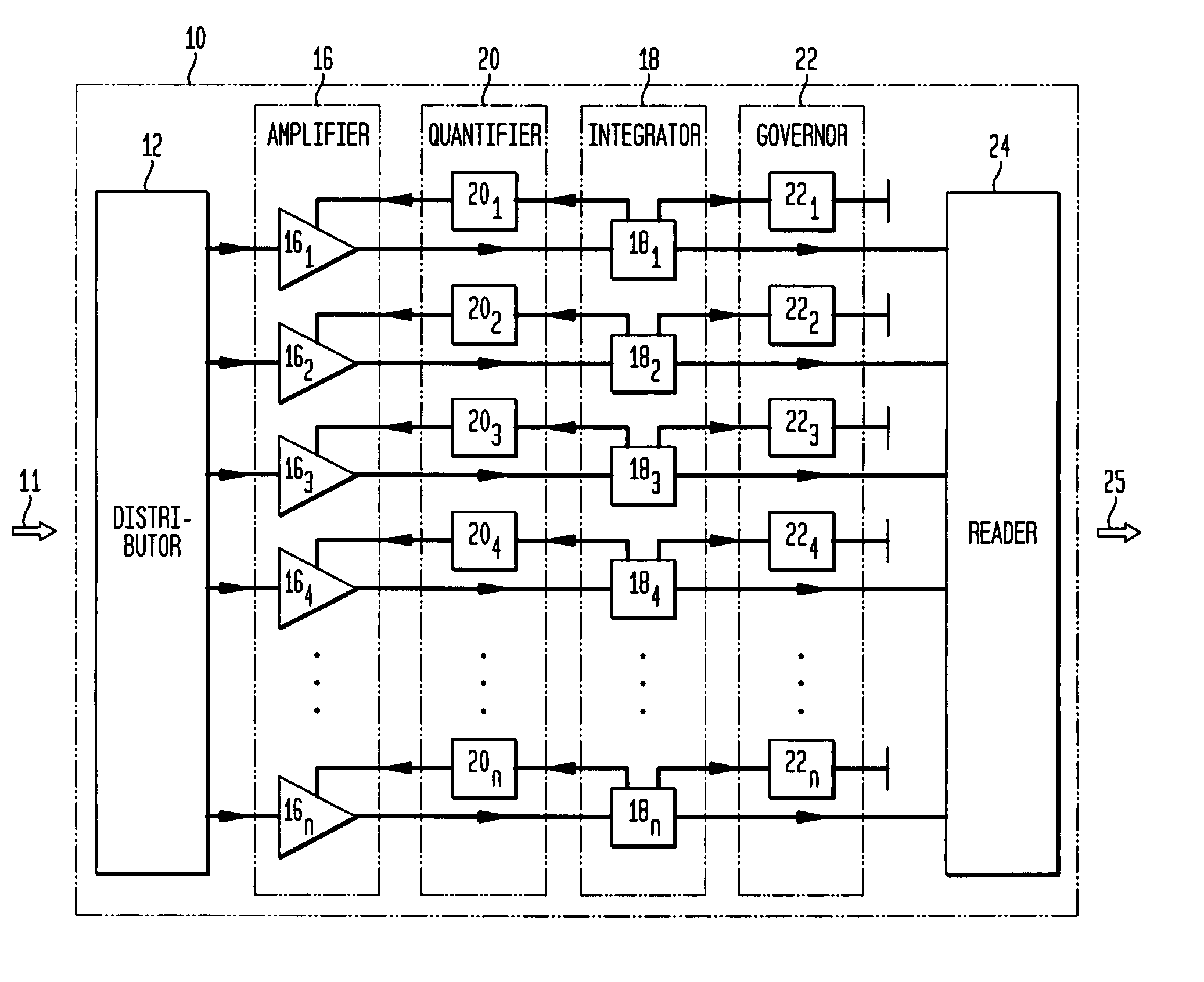
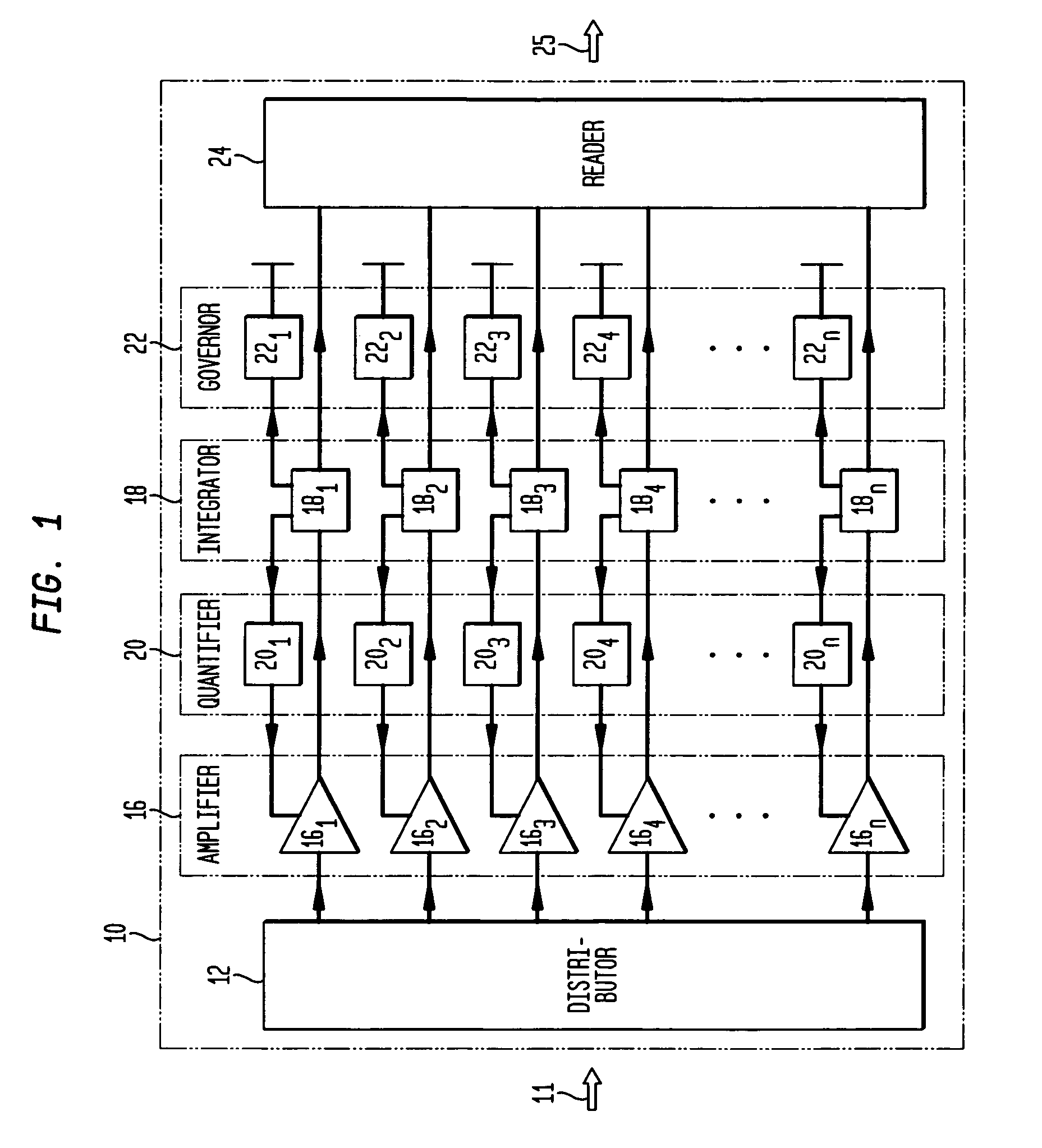
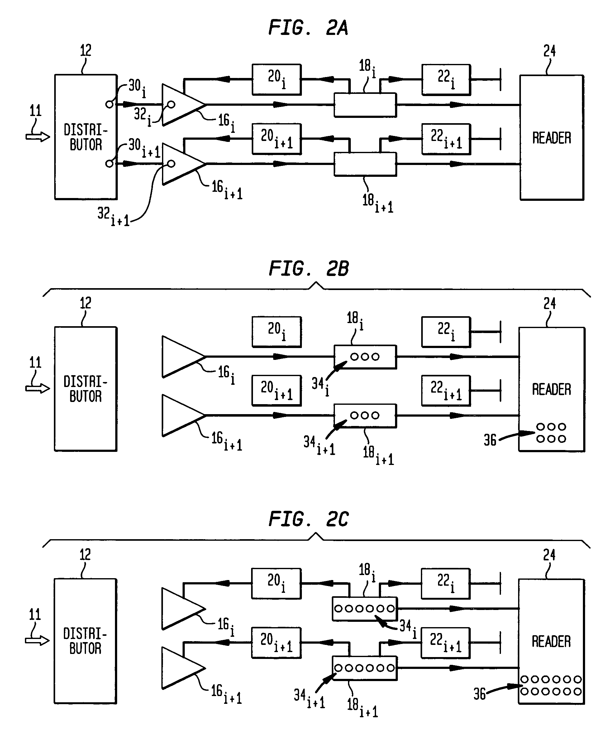
[0030]FIG. 1 shows an illustrative functional block diagram of a discrete amplifier 10 in accordance with an embodiment of the present invention. As depicted, discrete amplifier 10 is a multichannel amplifier, with each channel (referenced by subscript i, i=1, 2, 3, 4 . . . n) comprising an amplifier 16i responsive to a quantifier 20i and coupled to an integrator 18i, which is coupled to quantifier 20i and to governor 22i. A distributor 12 is responsive to an input signal 11 and provides an output coupled to the input of each channel amplifier 16i. A reader 24 is coupled to each integrator 18 and provides an amplified output signal 25 representative of input signal 11. Thus, discrete amplifier 10 may be viewed as a multichannel amplifier having a distributor 12 coupled to an amplifier stage 16, which is responsive to a quantifier stage 20 and is coupled to an integrator stage 18, which in turn is coupled to quantifier stage 20, governor stage 22 and reader 24. As will be further und...


PUM


Abstract

A system and method providing for the detection of an input signal by distributing the input signal into independent signal components that are independently amplified. Detection of an input signal comprises generating from the input signal a plurality of spatially separate elementary charge components, each having a respective known number of elementary charges, the number of the plurality of spatially separate elementary charge components being a known monotonic function of the magnitude of said input signal; and independently amplifying each of the plurality of spatially divided elementary charge components to provide a respective plurality of signal charge packets, each signal charge packet having a second number of elementary charges greater than the respective known number by a respective amplification factor.

Description

[0001]This is a continuation of application Ser. No. 10 / 208,530, filed Jul. 30, 2002 now U.S. Pat. No. 6,885,827.TECHNICAL FIELD[0002]The present invention relates generally to signal detection and, more particularly, to detecting a weak or low level signal, such as a weak optical or electrical signal, and preferably to detecting such a weak signal with high resolution of the signal magnitude.BACKGROUND OF THE INVENTION[0003]Recording and measuring a weak signal represented by, for example, one to several dozen elementary charge carriers presents challenging and acute problems for the designers of modern sensors and transducers for myriad applications in diverse fields of science and technology. In these sensors and transducers, various primary signals (optical, ultrasonic, mechanical, chemical, radiation, etc.) are transformed into elementary charge carriers, such as electrons, holes, or ions, depending on the specific types and versions of the devices being developed for this purp...

Claims


Application Information

Patent Timeline
Patent Type & Authority Patents(United States)
IPC IPC(8): H04B10/06G01T1/20G01T1/24H01L27/14H03F3/21H03F3/70
CPCH03F3/211H03F3/70H03F2203/21142H03F2203/21106
Inventor SHUSHAKOV, DMITRY A.SHUBIN, VITALY E.
Owner AMPLIFICATION TECH INC
Learn More