
MEMS tunable capacitor based on angular vertical comb drives

a vertical comb drive and capacitor technology, applied in the direction of variable capacitors, capacitors with electrode area variation, snap-action arrangements, etc., can solve the problems of limiting the tuning ratio to about 1.5:1 (50%), and not being expected to achieve widespread commercial use. , to achieve the effect of increasing the tuning range and appreciating the drawbacks inherent in lateral drive mems capacitors

Inactive Publication Date: 2006-08-01
RGT UNIV OF CALIFORNIA
View PDF5 Cites 82 Cited by
  • Summary
  • Abstract
  • Description
  • Claims
  • Application Information

AI Technical Summary

Benefits of technology

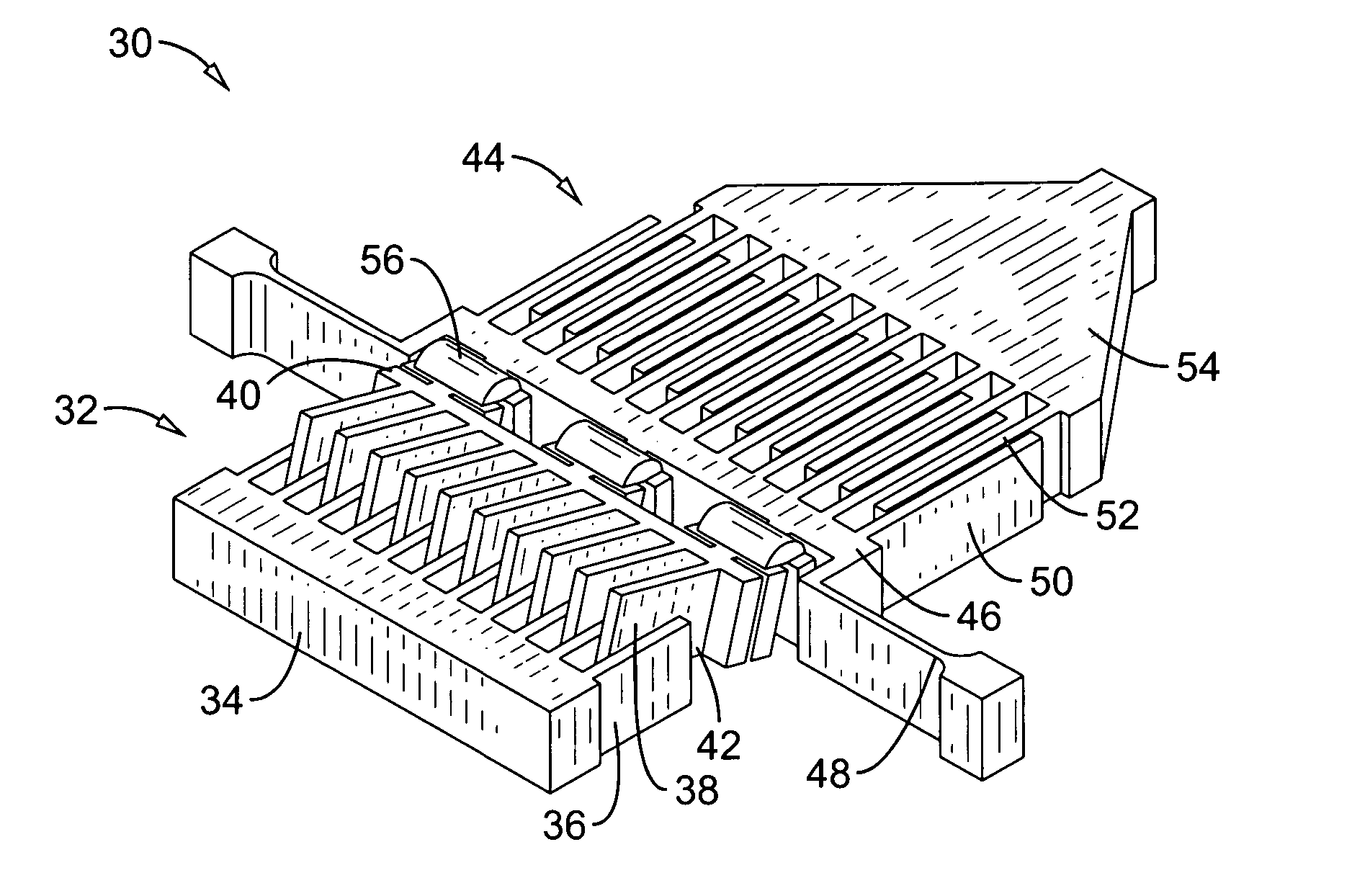
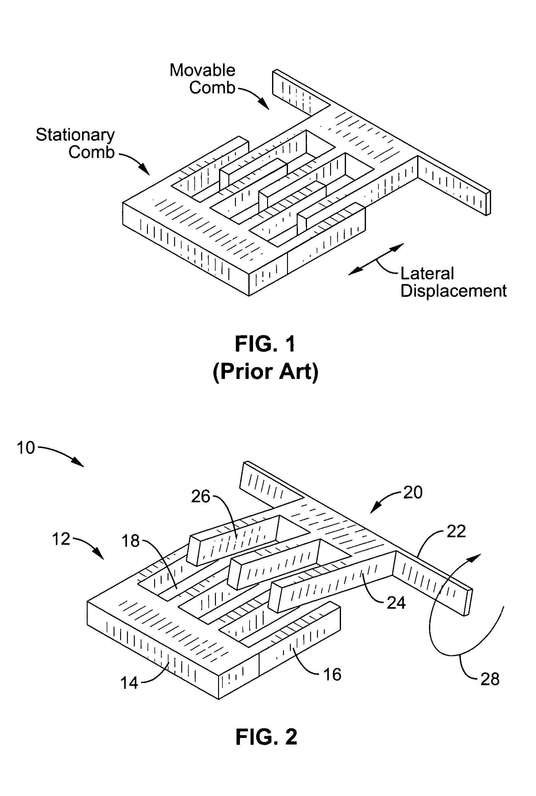
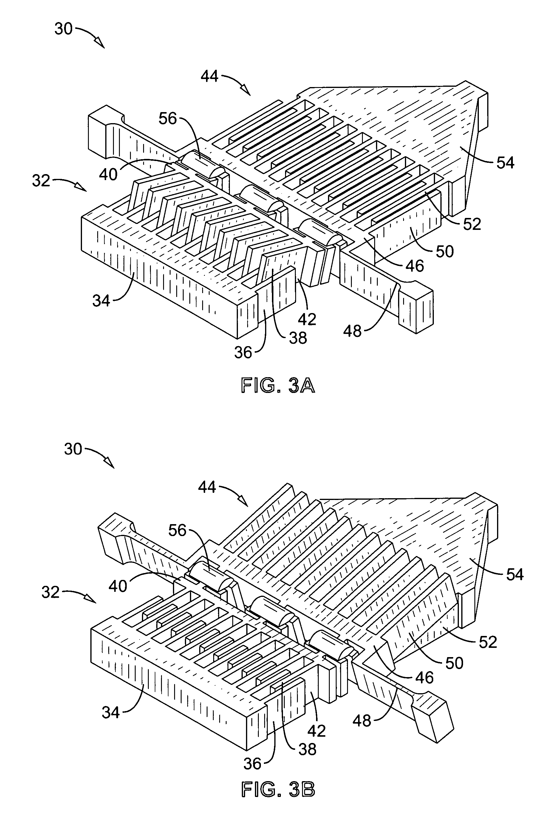
[0018]MEMS tunable capacitors in accordance with the present invention employ an angular vertical comb (AVC) structure with a variable level of interdigitation between the combs. This new device configuration fully appreciates the drawbacks inherent in lateral drive MEMS capacitors, and provides substantial improvements, such as increased tuning range.
[0036]Another aspect of the invention is to provide a MEMS tunable capacitor that can be readily fabricated with few process steps.

Problems solved by technology

However, their drawbacks have led to research in Micro-Electro-Mechanical Systems (MEMS) as a possible alternative technology in RF and microwave systems.
Although MEMS capacitors can provide superior performance over conventional devices, they are not expected to achieve widespread commercial use unless fabrication can be made more cost-effective.
However, these gap-closing actuators also suffer from some fundamental limitations.
For example, these devices exhibit highly nonlinear actuation and also exhibit a pull-in phenomenon at about one third of the gap distance between conductors, which limits the tuning ratio to about 1.5:1 (50%).
Nevertheless, the tuning ratios achieved are still very modest.
However, these modifications demonstrate only moderate increases.
Hence, the tuning ratio is limited by the maximum separation of these fingers and their overall lengths, which has the negative effect of increasing overall device size.
Despite the advantages of MEMS tunable capacitors, a fundamental limit exists for lateral comb drive devices; the lengths of the sensing fingers must be shorter than the total displacement of the comb drives.
The larger device size reduces the ability to effectively integrate the MEMS device into microwave systems.

Method used


Image

  • MEMS tunable capacitor based on angular vertical comb drives
  • MEMS tunable capacitor based on angular vertical comb drives
  • MEMS tunable capacitor based on angular vertical comb drives

Examples


Embodiment Construction

[0066]Referring more specifically to the drawings, for illustrative purposes the present invention is embodied in the apparatus generally shown in FIG. 2 through FIG. 26. It will be appreciated that the apparatus may vary as to configuration and as to details of the parts, and that the method may vary as to the specific steps and sequence, without departing from the basic concepts as disclosed herein.

[0067]Instead of relying on increasing and decreasing the depth of electrode finger interposition for tuning, as is accomplished within conventional MEMS lateral comb drive actuators, the present invention comprises a comb drive configured for angular displacement to change interdigitation and thus the exhibited capacitance. This new class of tunable capacitors is referred to herein as AVC tunable capacitors.

[0068]This section describes AVC tunable capacitors including results from our ongoing development of these devices. It will be appreciated that the later developed AVC capacitors a...


PUM


Abstract

A MEMS tunable capacitor with angular vertical comb-drive (AVC) actuators is described where high capacitances and a wide continuous tuning range is achieved in a compact space. The comb fingers rotate through a small vertical angle which allows a wider tuning range than in conventional lateral comb drive devices. Fabrication of the device is straightforward, and involves a single deep reactive ion etching step followed by release and out-of-plane assembly of the angular combs.

Description

CROSS-REFERENCE TO RELATED APPLICATIONS[0001]This application claims priority from U.S. provisional application Ser. No. 60 / 472,696 filed on May 21, 2003, incorporated herein by reference in its entirety.STATEMENT REGARDING FEDERALLY SPONSORED RESEARCH OR DEVELOPMENT[0002]Not ApplicableINCORPORATION-BY-REFERENCE OF MATERIAL SUBMITTED ON A COMPACT DISC[0003]Not ApplicableNOTICE OF MATERIAL SUBJECT TO COPYRIGHT PROTECTION[0004]A portion of the material in this patent document is subject to copyright protection under the copyright laws of the United States and of other countries. The owner of the copyright rights has no objection to the facsimile reproduction by anyone of the patent document or the patent disclosure, as it appears in the United States Patent and Trademark Office publicly available file or records, but otherwise reserves all copyright rights whatsoever. The copyright owner does not hereby waive any of its rights to have this patent document maintained in secrecy, includ...

Claims


Application Information

Patent Timeline
Patent Type & Authority Patents(United States)
IPC IPC(8): H01G7/00B81B5/00H01G5/06
CPCH01G5/06B81C1/00007B81B2201/0221B81B2203/0136
Inventor WU, MING C.NGUYEN, HUNG D.HAH, DOO-YOUNGPATTERSON, PAMELA R.
Owner RGT UNIV OF CALIFORNIA
Learn More