Range discriminating optical sensor having a wide angle lens with a fixed focal length

a wide angle lens and optical sensor technology, applied in the field of optical sensors, can solve the problems of limited field of view and quite limited depth of field, and achieve the effect of enhancing object blurring and increasing sensor resolution

Inactive Publication Date: 2006-08-01
VEONEER US LLC +1
View PDF10 Cites 0 Cited by
  • Summary
  • Abstract
  • Description
  • Claims
  • Application Information

AI Technical Summary

Benefits of technology

[0021]The image can be projected onto an electronic imaging element. The pixel size of the electronic imaging element can be selected to be quite small. A small pixel size increases the resolution of the sensor while at the same time enhancing the blurring of objects outside desired depth of field. The pixel size may depend on a number of parameters including the use of the sensor and the cost of the electronic imaging element. In most instances an electronic imaging element with a pixel size in the range from about 2 μm to about 6 μm will allow for proper recognition of objects. Alternatively, the electronic imaging element may have a pixel size in the range from about 3 μm to about 5 μm. In one presently preferred embodiment, the electronic imaging element has a pixel size of about 3 μm.
[0026]The design of the optical sensor with a large aperture and small pixel size creates a view with a short depth of field where objects in the foreground are in focus and objects in the background are blurred. A signal processor can be used to interpret this data. Because the objects outside of the depth of field are blurred, the signal processor can discriminate objects from the foreground and background of the view. Therefore, only objects in the foreground, which may present actual threats to the vehicle, are processed as potential threats to the vehicle by the algorithms of the signal processor. Moreover, other characteristics of the object such as velocity and size may also be determined by the signal processor. In this manner, the signal processor may determine that a vehicle safety feature should be activated or otherwise controlled.

Problems solved by technology

The combination of the small pixel size and the large aperture creates a depth of field that is quite limited.
This limited field of view blurs objects that are too close or too far away from the optical sensor such that only objects within a preselected range are in focus.

Method used


Image

  • Range discriminating optical sensor having a wide angle lens with a fixed focal length
  • Range discriminating optical sensor having a wide angle lens with a fixed focal length
  • Range discriminating optical sensor having a wide angle lens with a fixed focal length

Examples


Embodiment Construction

[0033]The presently preferred embodiments of the present invention will be best understood by reference to the drawings, wherein like parts are designated by like numerals throughout. It will be readily understood that the components of the present invention, as generally described and illustrated in the figures herein, could be arranged and designed in a wide variety of different configurations. Thus, the following more detailed description of the embodiments of the apparatus, system, and method of the present invention, as represented in FIGS. 1 through 4, is not intended to limit the scope of the invention, as claimed, but is merely representative of presently preferred embodiments of the invention.

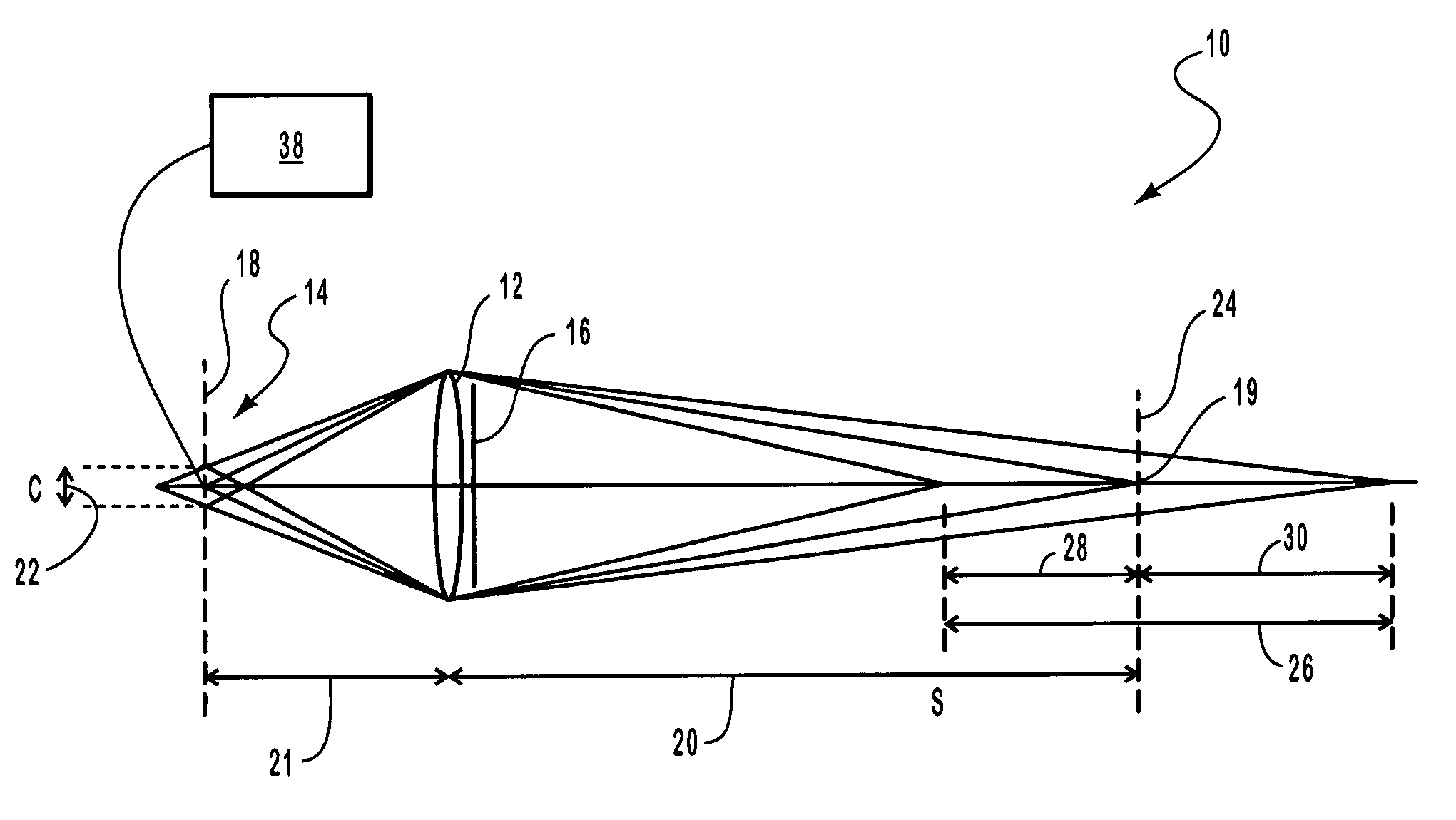
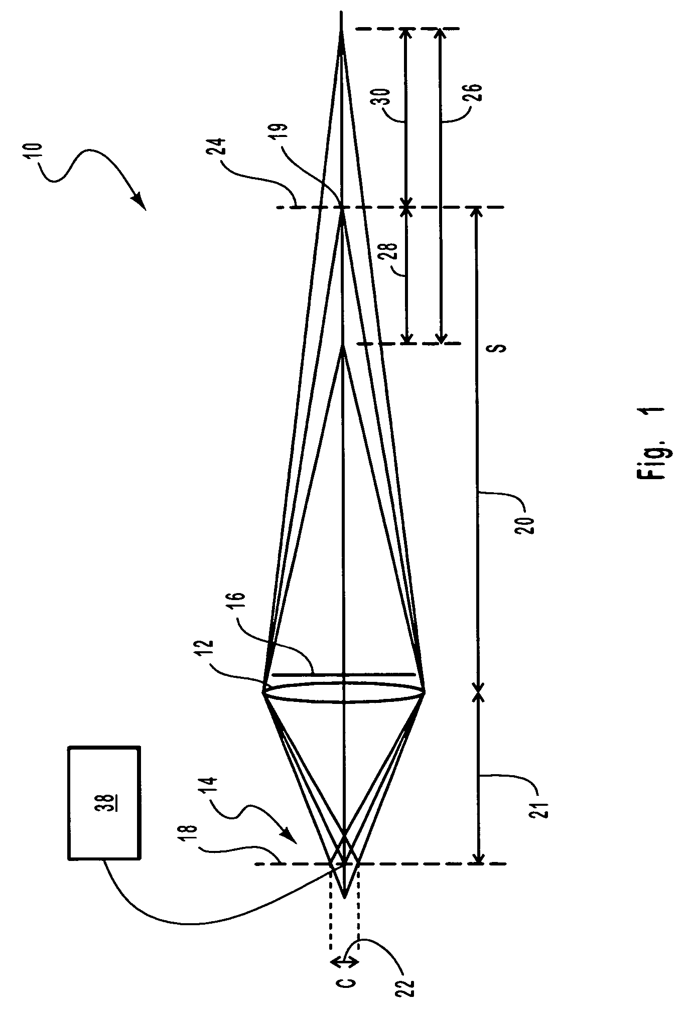
[0034]Referring to FIG. 1, a schematic ray diagram illustrating a range discriminating optical sensor 10 of the present invention is shown. The optical sensor 10 can discriminate objects in the image based on their relative range from the lens 12 of the optical sensor 10. This range di...


PUM


Abstract

A range discriminating optical sensor for use in a vehicle safety system is provided. The range discriminating sensor is designed to create a small depth of field such that objects at a range outside of the depth of field are eliminated from the image. Generally, the optical sensor uses a large aperture to limit the depth of field. An electronic imaging element is used to detect the image projected by the lens. The electronic imaging element may have a small pixel size which further reduces the depth of field. A signal processor can be used to determine the distance from the image sensor with objects with the selected depth of field appearing in focus and those outside of the depth of field appearing out of focus.

Description

BACKGROUND OF THE INVENTION[0001]1. Field of the Invention[0002]The present invention relates to sensors which can be used to activate or otherwise control vehicle safety systems. More specifically, the present invention relates to an optical sensor which can discriminate between objects based upon range from the sensor.[0003]2. Technical Background[0004]Vehicle safety is a significant concern to consumers and manufacturers alike. A number of features have been designed which make automobiles safer to operate. Some of the earliest features designed to make vehicles safer are devices designed to protect the vehicles and their occupants from impact. These devices are passive in nature requiring no action from the driver to activate them. Such safety features include bumpers and reinforced body panels and vehicle frame.[0005]As the design of vehicles has advanced, so have the number and complexity of their safety features. The advent of the seatbelt was a significant advancement in veh...

Claims


Application Information

Patent Timeline
Patent Type & Authority Patents(United States)
IPC IPC(8): H01L27/00B60R21/01B60R21/0134G01C3/32G01S11/12
CPCG01S11/12G01C3/32B60R21/0134
Inventor DECKER, STEPHEN W.DEMERSSEMAN, BERNARD
Owner VEONEER US LLC
Why Eureka
Try Eureka