
Wood chipper having an infeed chute safety device

a safety device and wood chipper technology, applied in the field of controlled feed devices, can solve the problems of operator injury, dangerous device operation, dangerous area which may catch an operator's clothing, etc., and achieve the effect of preventing or minimizing operator injury, effective and easy operation

Inactive Publication Date: 2006-08-01
REASONABLE SOLUTIONS
View PDF9 Cites 19 Cited by
  • Summary
  • Abstract
  • Description
  • Claims
  • Application Information

AI Technical Summary

Benefits of technology

[0004]The present invention overcomes the aforementioned shortcomings and provides a wood chipper safety device that is effective and easy to operate in an emergency situation, thus preventing or minimizing operator injury. In one embodiment, a wood chipper safety device includes an elongated structure positioned outside of and adjacent to the infeed chute of a wood chipper, the elongated structure movable vertically downward between a plurality of positions, and an actuator operably connected to the elongated structure, the actuator having a plurality of operable positions corresponding to the plurality of positions of the elongated structure. The plurality of operable positions of the actuator permit, interrupt, or reverse the motive operation of the powered feed and cutting systems of the wood chipper.

Problems solved by technology

Wood chippers, if operated incorrectly, are potentially dangerous devices.
The feed system, located at the narrowest point of the infeed chute, is a dangerous area which may catch an operator's clothing or, more importantly, an operator's limb if he or she improperly reaches into the infeed chute during operation of the wood chipper.
Although marginally effective, these safety devices suffer from the fact that their effectiveness is limited by the inattentiveness of an operator and that they are difficult to operate in an emergency situation.

Method used


Image

  • Wood chipper having an infeed chute safety device
  • Wood chipper having an infeed chute safety device
  • Wood chipper having an infeed chute safety device

Examples


Embodiment Construction

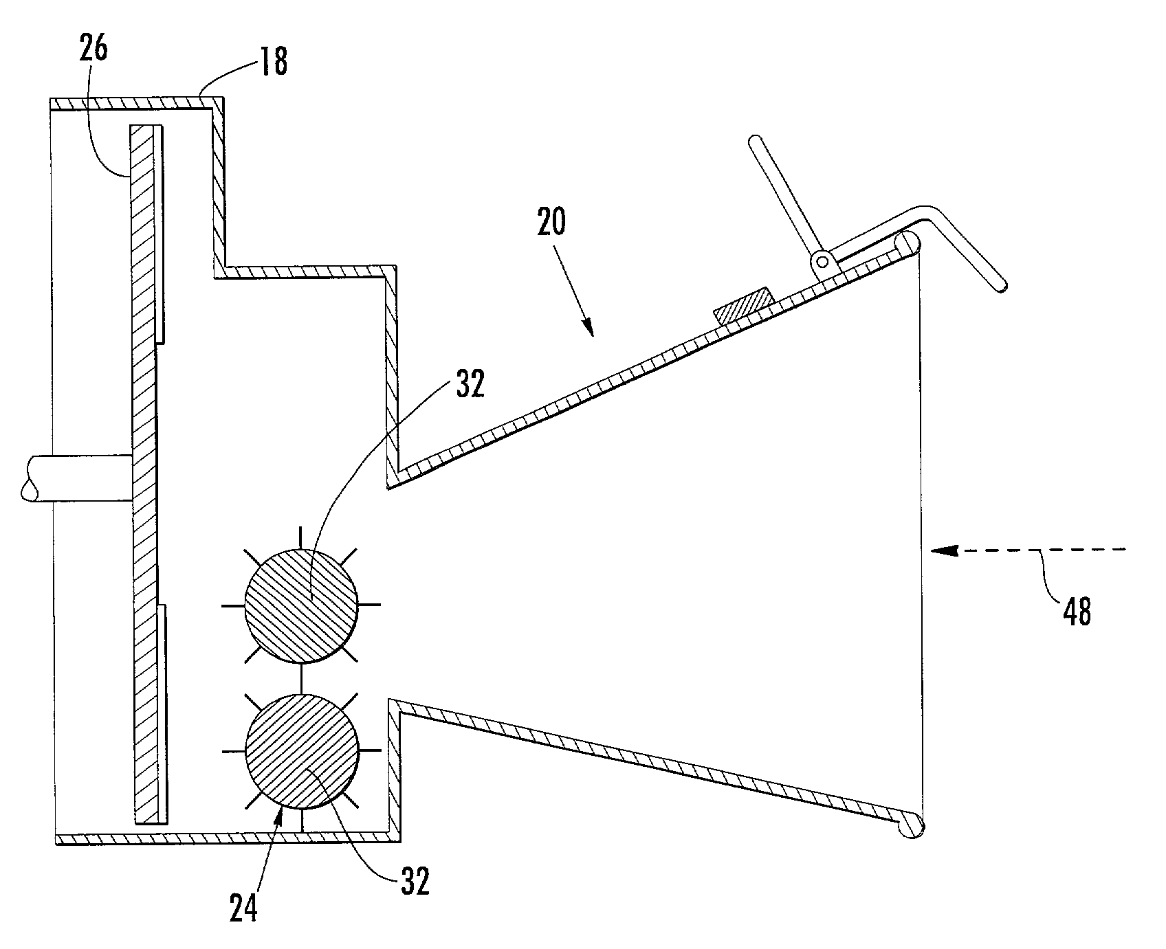
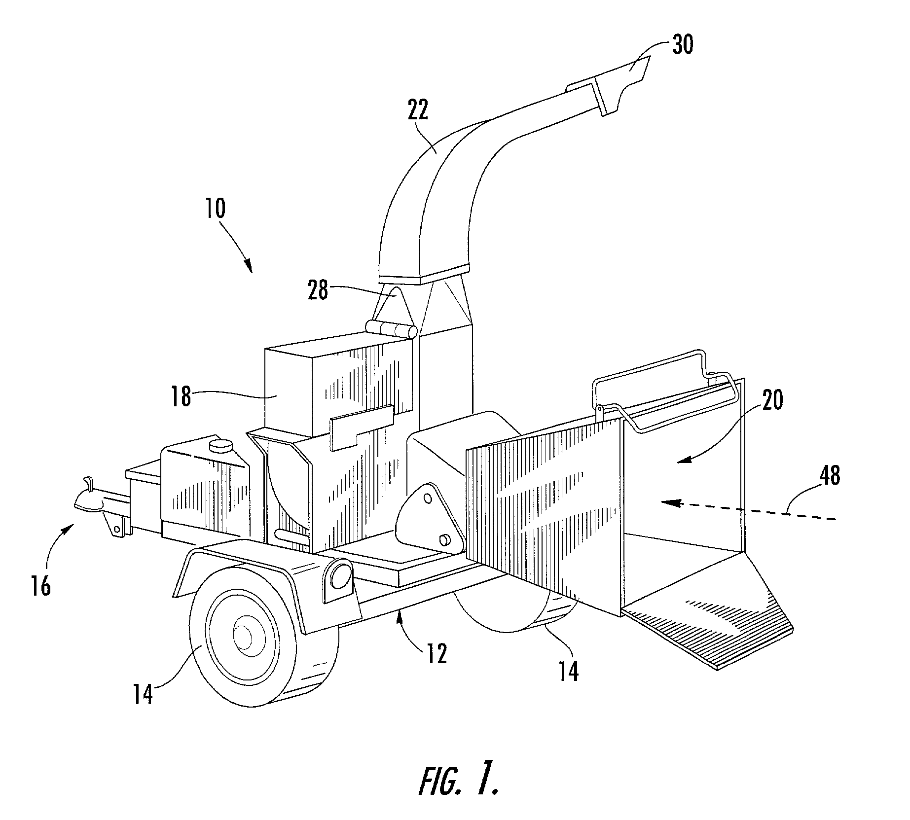
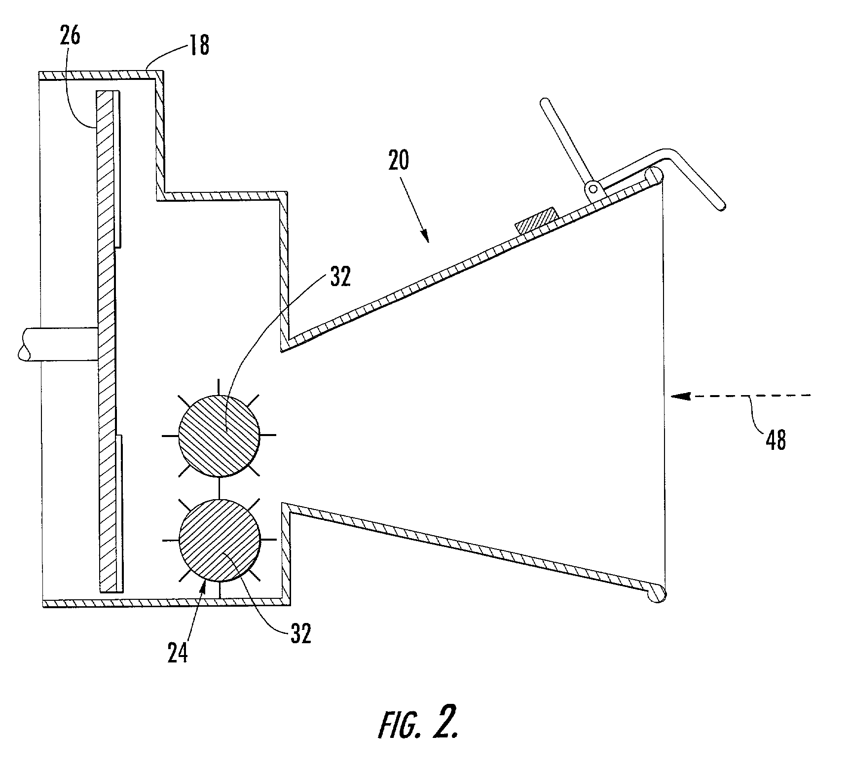
[0010]Referring to FIGS. 1 and 2, in one embodiment, a wood chipper 10 includes a frame 12 supported by a pair of wheels 14 and a conventional trailer hitch 16. The trailer hitch 16 allows the chipper 10 to be towed by a vehicle. A chipper hood 18, an infeed chute 20, and a discharge chute 22 are supported on the frame 12. An internal combustion engine may also be supported on the frame 12 for providing rotational energy to both a feed wheel system 24 and a cutting blade 26. The chipper hood 18 encloses the rotary cutting mechanism or blade 26 to prevent high-velocity pieces of wood from exiting the wood chipper 10 before being expelled through the discharge chute 22. A swivel bracket 28 may be mounted between the chipper assembly 18 and the discharge chute 22, allowing the discharge chute 22 to be to be rotatably aligned to expel wood chips in a desired direction. Additionally, the discharge chute 22 may include an adjustable deflector 30 mounted at the discharge chute exit for all...


PUM


Abstract

A waste reducing device, such as a wood chipper, having an infeed chute, a powered feed system, a powered cutting system, a discharge chute, and a safety device including an elongated structure positioned outside of and adjacent to the infeed chute of the wood chipper, the elongated structure movable vertically downward and radially inward towards the infeed chute between a plurality of positions, and an actuator operably connected to the elongated structure, the actuator having a plurality of operable positions corresponding to the plurality of positions of the elongated structure. The plurality of operable positions of the actuator permitting, interrupting, or reversing the motive operation of the powered feed and cutting systems of the wood chipper.

Description

FIELD OF THE INVENTION[0001]The present invention relates generally to a controlled feed device having an associated safety device and, more specifically, to a waste reducing device, such as a wood chipper, having an infeed chute safety device.BACKGROUND OF THE INVENTION[0002]Wood chippers are used to reduce branches, trees, brush, and other bulk wood products into small wood chips. A wood chipper typically includes an infeed chute, a feed system for controlling the feed rate of wood products into the chipper, a wood chipping mechanism, a drive system for powering the feed system and the chipping mechanism, and a discharge chute. The infeed chute is typically a funnel-shaped conduit with a wide opening which tapers towards the feed system, converging the wood products towards the chipping mechanism. Through the operation of the feed system, wood products are brought into contact with the chipping mechanism, which grinds, flails, or cuts the wood products into small pieces. These woo...

Claims


Application Information

Patent Timeline
Patent Type & Authority Patents(United States)
IPC IPC(8): B02C25/00A01G3/00B02C18/22B02C23/04
CPCA01G3/002B02C23/04B02C18/2225B02C2201/066
Inventor BEAM, III, DENNIS A.
Owner REASONABLE SOLUTIONS
Learn More