Color correction of images
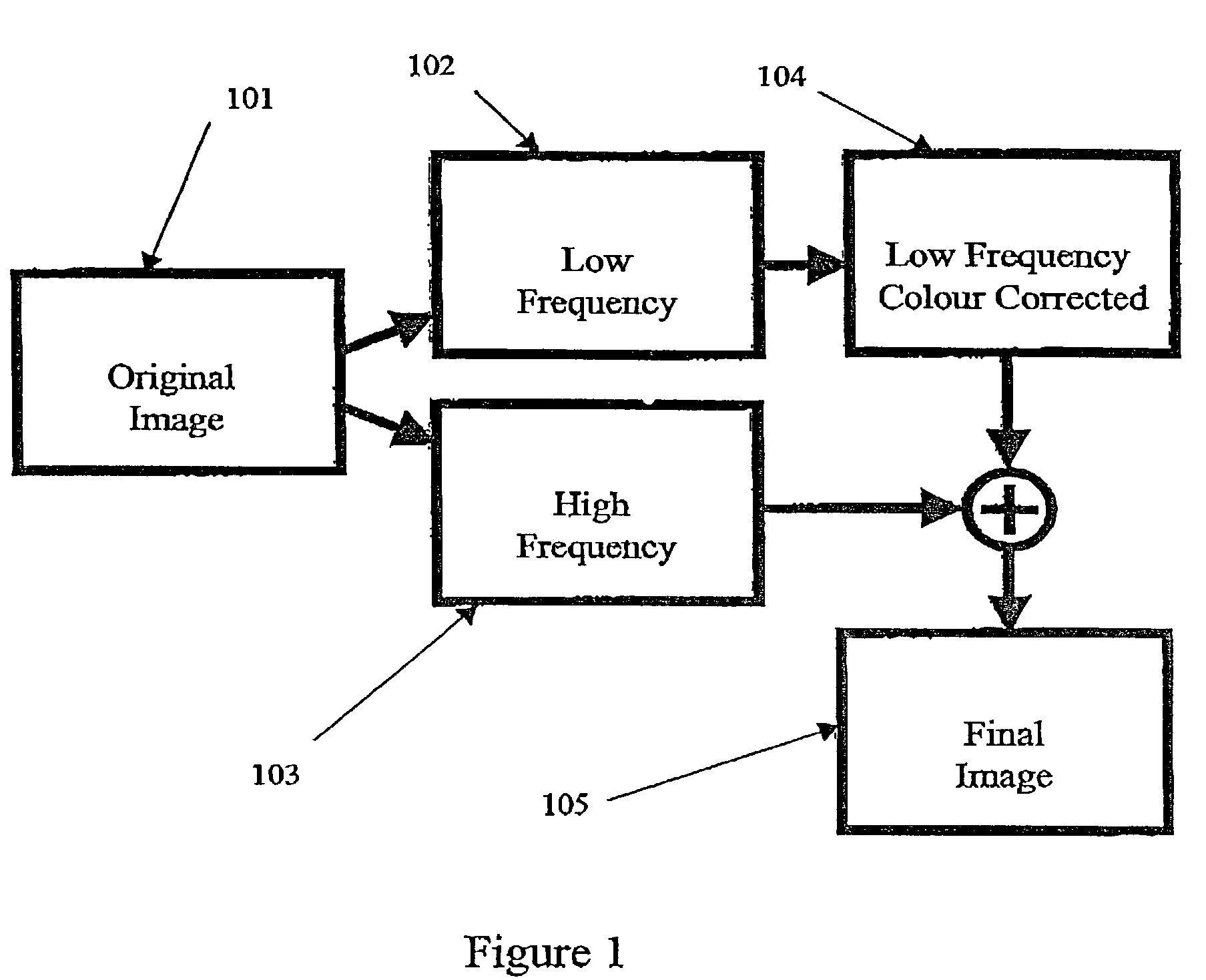
a color correction and image technology, applied in the field of color correction of images, can solve the problems of difficult to construct color filters for sensors, and the amount of computation required may be a significant issue or restraint, and achieve the effect of high spatial frequency
- Summary
- Abstract
- Description
- Claims
- Application Information
AI Technical Summary
Problems solved by technology
Method used
Image
Examples
example 1
Demosaicing in a Consumer Digital Camera
[0081]FIG. 6 shows one example of a consumer imaging device, here a hand-held digital camera 1. Such cameras have a colour image sensor 2 having a two-dimensional regular array of imaging elements or pixels 4. A typical consumer sensor array may have up to 4 Megapixels resolution, arranged in a rectangular array 2500 pixels wide and 1600 pixels high.
[0082]The imaging elements are sensitive to light across a wide spectrum of colours, and so the sensor array 2 is overlain by a mosaic-like pattern of colour filters 6. There are usually only three such colours, red (R), green (G) and blue (B), (RGB) and the colours are usually interleaved in a repeating pattern across the sensor array 2. Thus, the array elements 4 under each colour of filter 6 are sensitive only to light with wavelengths passed by each corresponding filter 6
[0083]Many filter patterns exist, but the most common is the Bayer filter pattern. This consists of pixels with colour filter...
example 2
RGB Correction
[0107]The invention can also be applied to cases where each location in the original colour image has overlapping or coincident pixels of multiple colour values. Such images can be generated by imaging systems having three CCD sensors, by flatbed colour scanners, or other imaging systems in which the colour image is formed from sets of separate, registered RGB images. Colour correction will generally be required as the RGB space of such imaging systems will typically need modification to an RGB space appropriate for human viewing.
[0108]The basic elements of an exemplary digital camera system of this type (and the general processing steps associated with image formation) may be essentially as shown in FIGS. 11 and 12. The difference is that sensor 76 is not a charge coupled device with an imaging area 77 covered with a filter mosaic, but instead a sensor of the type described in, for example, U.S. Pat. No. 5,965,875 in which separate photodiodes for each channel are pro...
example 3
Colour Space Transformation
[0110]As indicated above, embodiments of the present invention can be applied to a number of contexts in which colour correction is required. In the cases described above in Examples 1 and 2, minor correction is required (typically from one RGB space to another) rather than major transformation. The goal of using such a colour correction mechanism in Examples 1 and 2 is to map between the RGB spaces of various physical input and output devices in a manner that is pleasing to the human visual system
[0111]It is sometimes convenient or desirable to convert to a colour space that is not RGB. Aspects of the present invention may be employed for such transformation to achieve benefits in noise reduction. One circumstance where this may apply is in mapping of an image into a different colour space [CMYK] for printing.
[0112]Colour space transformation to a colour space that is not RGB may most effectively be achieved in two stages by first mapping from a device RG...
PUM
 Abstract
Description
Claims
Application Information
 - R&D
- Intellectual Property
- Life Sciences
- Materials
- Tech Scout
- Unparalleled Data Quality
- Higher Quality Content
- 60% Fewer Hallucinations
Browse by: Latest US Patents, China's latest patents, Technical Efficacy Thesaurus, Application Domain, Technology Topic, Popular Technical Reports.
© 2025 PatSnap. All rights reserved.Legal|Privacy policy|Modern Slavery Act Transparency Statement|Sitemap|About US| Contact US: help@patsnap.com


