Aerosol separator; and method

a technology of separator and aerosol, which is applied in the direction of separation process, filtration separation, combustion air/fuel air treatment, etc., can solve the problem of carrying substantial amounts of fine contaminan

Inactive Publication Date: 2006-07-25
DONALDSON CO INC
View PDF131 Cites 91 Cited by
  • Summary
  • Abstract
  • Description
  • Claims
  • Application Information

AI Technical Summary

Problems solved by technology

In addition, such gas streams also carry substantial amounts of fine contaminant, such as carbon contaminants.

Method used


Image

  • Aerosol separator; and method
  • Aerosol separator; and method
  • Aerosol separator; and method

Examples


Embodiment Construction

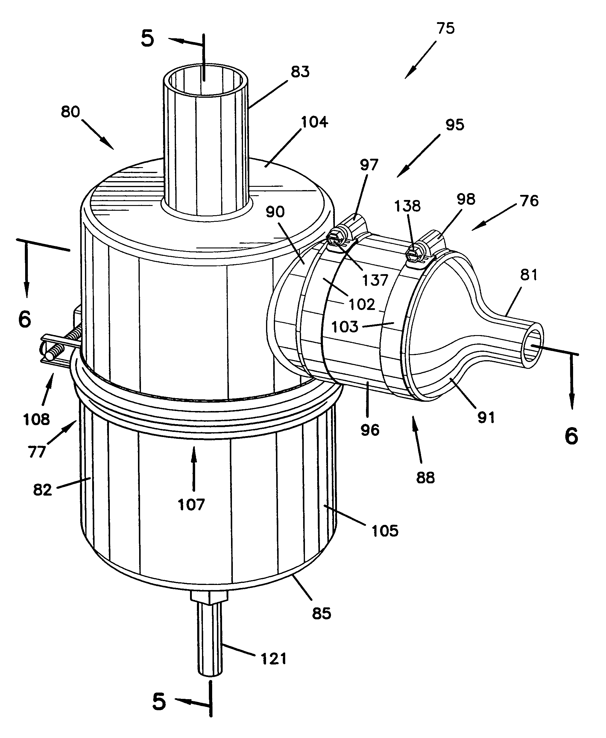
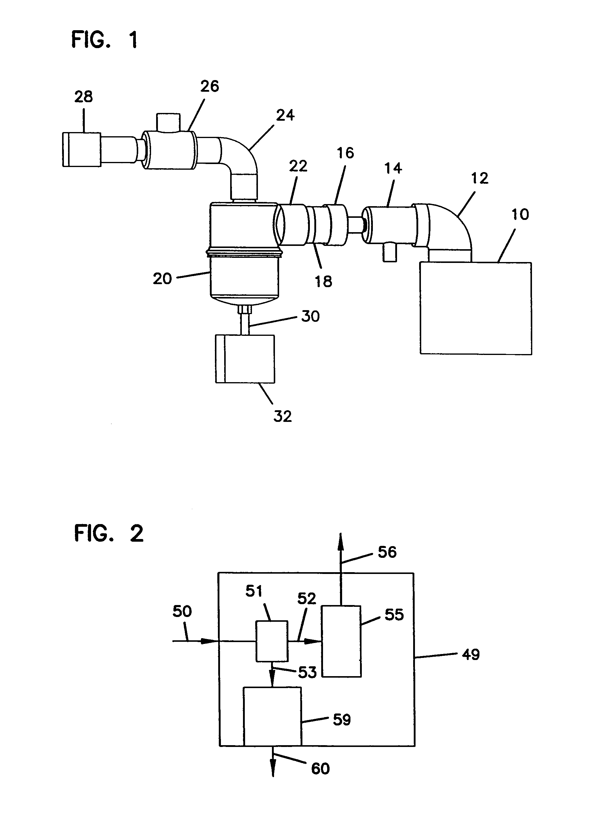
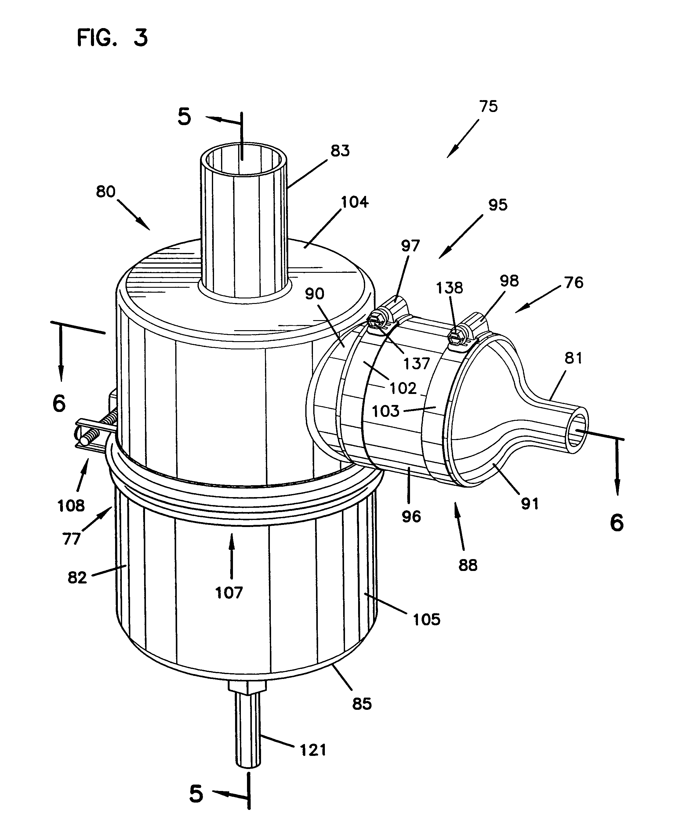
I. A Typical Application—Engine Crankcase Breather Filter

[0045]Pressure-charged diesel engines often generate “blow-by” gases, i.e., a flow of air-fuel mixture leaking past pistons from the combustion chambers. Such “blow-by gases” generally comprise a gas phase, for example air or combustion off gases, carrying therein: (a) oil or fuel aerosol principally comprising 0.1–5.0 micron droplets; and, (b) carbon contaminant from combustion, typically comprising carbon particles, a majority of which are about 0.1–10 microns in size. Such “blow-by gases” are generally directed outwardly from the engine block, through a blow-by vent.

[0046]Herein when the term “hydrophobic” fluids is used in reference to the entrained liquid aerosol in gas flow, reference is meant to nonaqueous fluids, especially oils. Generally such materials are immiscible in water. Herein the term “gas” or variants thereof, used in connection with the carrier fluid, refers to air, combustion off gases, and other carrier g...


PUM

PropertyMeasurementUnit
thicknessaaaaaaaaaa
diameteraaaaaaaaaa
diameteraaaaaaaaaa

Abstract

An arrangement for separating a hydrophobic liquid phase from a gaseous stream includes a coalescer filter, a housing, a gas flow direction arrangement, and a liquid collection arrangement. The coalescer filter includes a non-woven media of fibers. The housing includes an interior having a gas flow inlet and a gas flow outlet. The liquid collection arrangement is positioned within the housing construction and is oriented for receiving liquid collected from the coalescer filter and drained therefrom. Methods for conducting the separations are also provided.

Description

CROSS REFERENCE TO RELATED APPLICATIONS[0001]This application is a continuation of application Ser. No. 10 / 402,918, filed Mar. 28, 2003, to issue as U.S. Pat. No. 6,758,873 on Jul. 6, 2004. application Ser. No. 10 / 402,918 is a continuation of application Ser. No. 10 / 060,122, filed Jan. 28, 2002, U.S. Pat. No. 6,540,801 on Apr. 1, 2003. application Ser. No. 10 / 060,122 is a continuation of application Ser. No. 09 / 756,098, filed Jan. 8, 2001, U.S. Pat. No. 6,355,076. application Ser. No. 09 / 756,098 is a continuation of application Ser. No. 09 / 010,098, filed Jan. 21, 1998, U.S. Pat. No. 6,171,355. application Ser. No. 09 / 010,098 is a continuation-in-part of application Ser. No. 08 / 884,294, filed Jun. 27, 1997, U.S. Pat. No. 5,853,439. application Ser. Nos. 10 / 402,918; 10 / 060,122; 09 / 756,098; 09 / 010,098; and 08 / 884,294 are incorporated herein by reference.FIELD OF THE INVENTION[0002]The present invention relates to systems and methods for separating hydrophobic fluids (such as oils) whic...

Claims


Application Information

Patent Timeline
Patent Type & Authority Patents(United States)
IPC IPC(8): B01D46/00B01D46/10B01D46/12B01D46/24B01D46/52F01M13/04
CPCB01D46/001B01D46/0012B01D46/0023B01D46/003B01D46/0031B01D46/0087B01D46/2411B01D46/521F01M13/04B01D46/10Y10S55/19B01D2267/40F01M2013/0427F01M2013/0438B01D46/62
Inventor GIESEKE, STEVEN SCOTTDUSHEK, ROBERT ALLEN
Owner DONALDSON CO INC
Why Eureka
Try Eureka