
Self-locking suture anchor

a self-locking, suture technology, applied in the field of surgical fasteners, can solve problems such as weak interference fi

Inactive Publication Date: 2006-07-25
ETHICON INC
View PDF134 Cites 422 Cited by
  • Summary
  • Abstract
  • Description
  • Claims
  • Application Information

AI Technical Summary

Benefits of technology

Enables secure tissue attachment without knots, allowing for adjustable tension and reduced discomfort, with the ability to tighten or loosen the suture as needed, and can be used in various tissues without protruding above the tissue surface.

Problems solved by technology

However, the interference fit is weak enough to allow the suture to be pulled longitudinally through the cavity by a stronger force.

Method used


Image

  • Self-locking suture anchor
  • Self-locking suture anchor
  • Self-locking suture anchor

Examples


Embodiment Construction

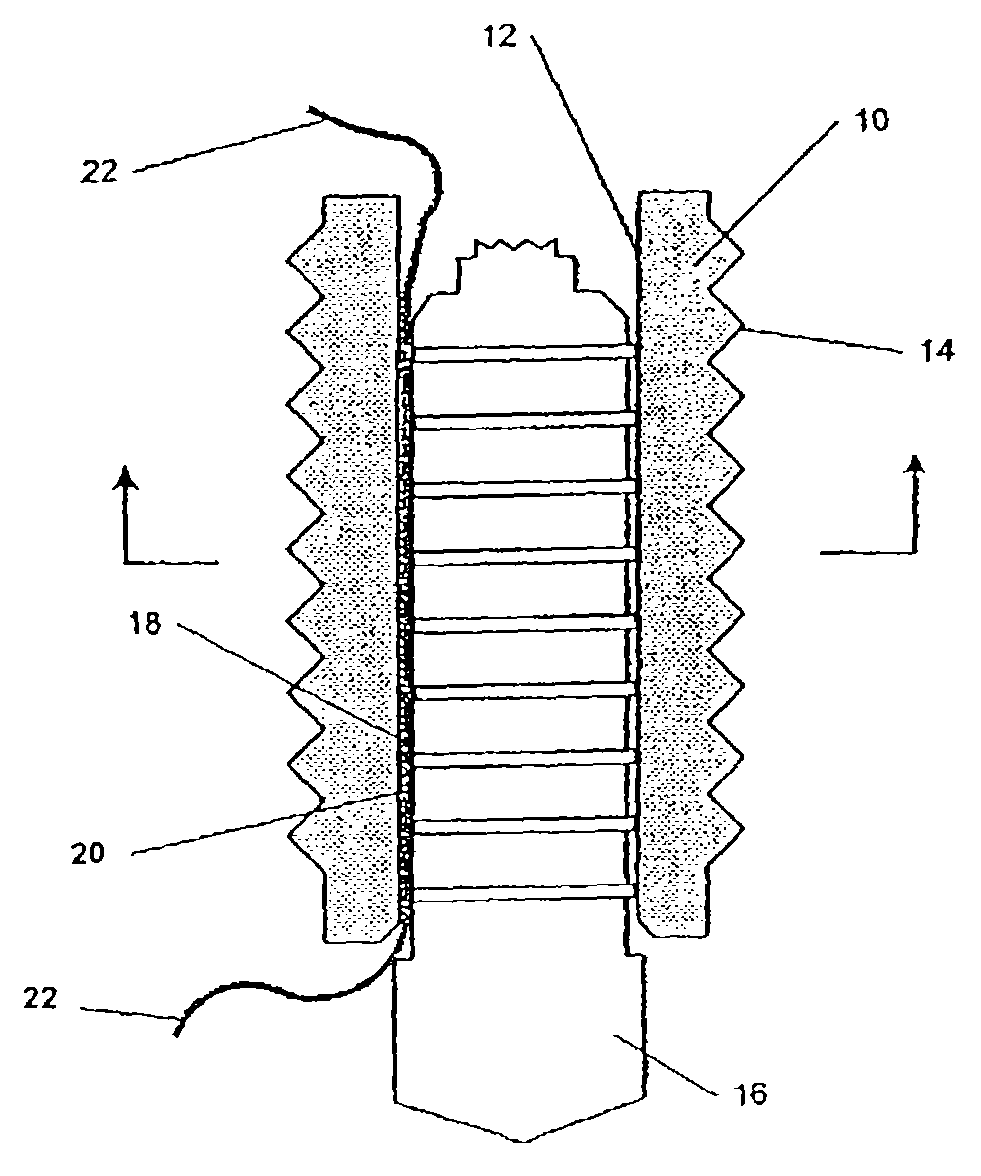
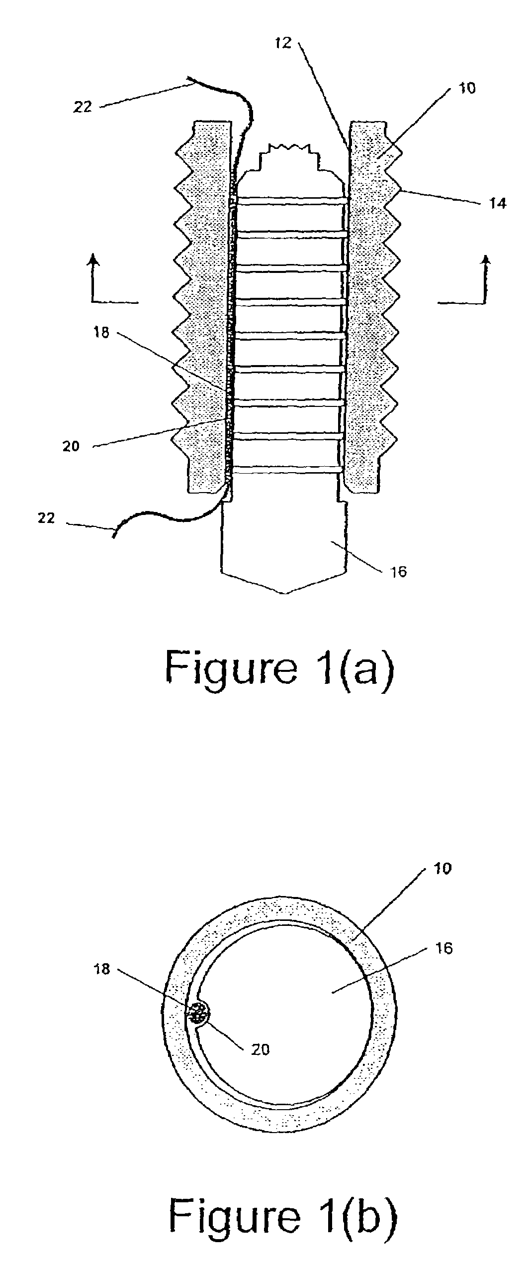
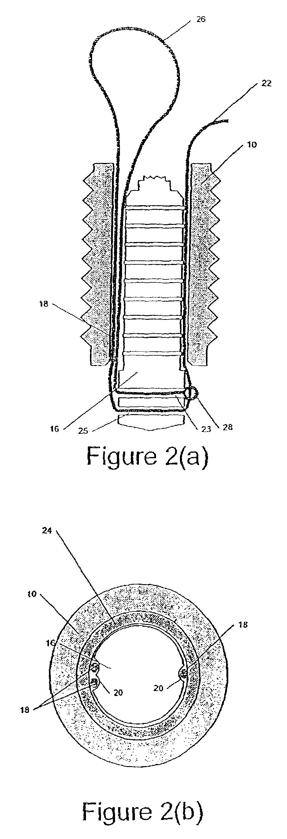
[0019]FIG. 1a shows a cutaway view of a suture anchor according to the invention. The anchor comprises an anchoring element 10, which is adapted to be embedded in a bone tunnel or in soft tissue, and comprises an axial channel 12. In the embodiment shown, element 10 comprises a series of ridges 14 on its outer surface, which aid in securing the element, for example, in a bone tunnel. It will be understood that the ridges 14 are not a necessary element of the anchor, and may be omitted if desired. The anchor 10 further comprises an insertion stem 16. When the anchor is in the deployed position shown in FIG. 1a, the insertion stem 16 is held within the axial channel 12, e.g., by interference fit. In preferred embodiments, the insertion stem 16 is slightly larger than the axial channel 12, so that the stem 16 forces the anchoring element 10 to expand when it is inserted therein, thereby securing the anchor firmly in the bone tunnel.

[0020]The anchor further comprises a filament 18, e.g....


PUM


Abstract

A tissue anchor having a length of filament held so that an applied force greater than a threshold force will cause the filament to move longitudinally, while an applied force less than the threshold force will not move the filament, and methods of attaching soft, tissue to bone using such an anchor.

Description

CROSS-REFERENCE TO RELATED APPLICATIONS[0001]This application is a continuation of application Ser. No. 10 / 375,389 Feb. 27, 2003 U.S. Pat. No. 6,660,023 filed on Feb. 27, 2003 and entitled “Self-Locking Suture Anchor,” which is a continuation of application Ser. No. 09 / 371,411 Aug. 10, 1999 U.S. Pat. No. 6,527,794 filed on Aug. 10, 1999 and entitled “Self-locking Suture Anchor.” These references are hereby incorporated by reference in their entirety.BACKGROUND OF THE INVENTION[0002]This invention relates to surgical fasteners, e.g., anchors that secure sutures to bone, a meniscus, or other tissue. It further relates to a suture anchor that attaches a suture to tissue without the use of knots, and to methods of securing tissue using one or more anchors and a length of suture.[0003]Many surgical procedures require the attachment of soft tissue, e.g., ligament or tendon grafts, to bone. This is typically accomplished by anchoring a suture in bone, for example with a screw, pin, or othe...

Claims


Application Information

Patent Timeline
Patent Type & Authority Patents(United States)
IPC IPC(8): A61B17/04A61B19/00
CPCA61B17/0401A61F2/0811A61F2002/0882A61B2017/00862A61B2017/0403A61B2017/0408A61B2017/0412A61B2017/0414A61B2017/0424A61B2017/0427A61B2017/0438A61B2017/044A61B2017/045A61B2017/0458A61B2017/0459A61B2019/307A61B19/30A61B90/03A61B2090/037
Inventor MCDEVITT, DENNISHALBRECHT, JEFFREYCASPARI, RICHARD
Owner ETHICON INC
Learn More