Motor mounting and sealing arrangement for a power tool

a technology for power tools and motors, applied in the direction of portable power-driven tools, manufacturing tools, drilling machines, etc., can solve the problems of relatively complex assembly process and fair arrangement of components, and achieve the effect of simplifying the fixing of the motor sub-assembly with respect to the gear casing

Inactive Publication Date: 2006-07-25
BLACK & DECKER INC
View PDF16 Cites 8 Cited by
  • Summary
  • Abstract
  • Description
  • Claims
  • Application Information

AI Technical Summary

Benefits of technology

[0004]The present invention aims to provide a hand held electrically powered tool in which the fixing of the motor sub-assembly with respect to the gear casing is simplified, both in terms of the components used and of the assembly process required.
[0010]By moulding on the seal and O-ring, separate components are not required for the functions of sealing between the motor plate and armature shaft and for the rotational fixing of the outer race of the armature bearing. With fewer components assembly of the tool or sub-assembly is correspondingly simplified. Also, by moulding the rings on, the rings are accurately located in the desired position, which may not always be the case with separately assembled rings.
[0013]In an alternative embodiment, the resilient sealing ring and the resilient O-ring are moulded onto a metal ring which metal ring may be fitted within the central opening of the motor plate. This embodiment has the advantage of it being simpler to mould the moulded on rings onto the metal ring than directly onto the motor plate. However, an additional component, the metal ring, is required and an additional assembly step, the fitting of the metal ring to the motor plate, is also required. The metal ring may have an axially extending portion and the resilient sealing ring may comprise a first portion moulded over the axially extending portion and a second portion depending from the first portion and forming a seal against the armature shaft. In this case, the first portion of the resilient sealing ring may have a U-shaped radial cross-section which may fit over an end of the axially extending portion of the metal ring and the second portion may have a V-shaped radial cross-section and depend from the radially innermost corner of the U-shaped portion. The first portion may help to form a deformable releasable coupling between the metal ring and the motor plate. The metal ring may also have a radially outwardly extending portion or flange and the resilient O-ring may be formed on a face of the radially extending portion.

Problems solved by technology

Traditionally separate components may be used for providing the multiple functions described above, which may lead to a fairly complex arrangement of components and may lead to a relatively complex assembly process for assembling the motor sub-assembly with respect to the gear casing sub-assembly.

Method used


Image

  • Motor mounting and sealing arrangement for a power tool
  • Motor mounting and sealing arrangement for a power tool
  • Motor mounting and sealing arrangement for a power tool

Examples


Embodiment Construction

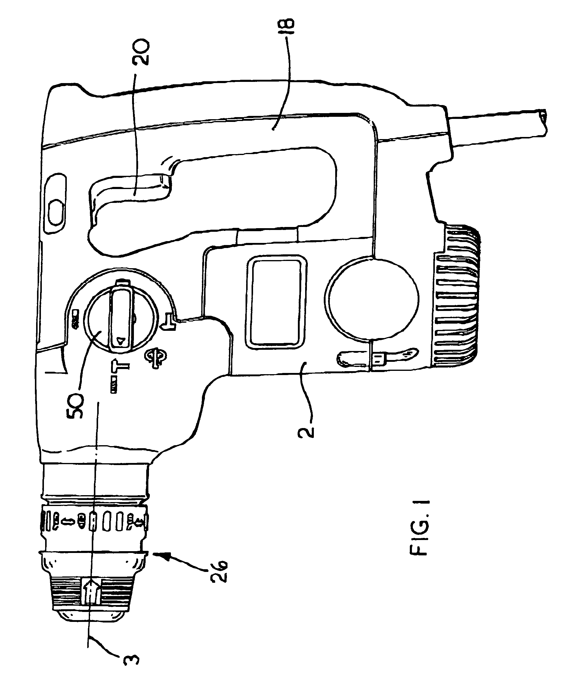
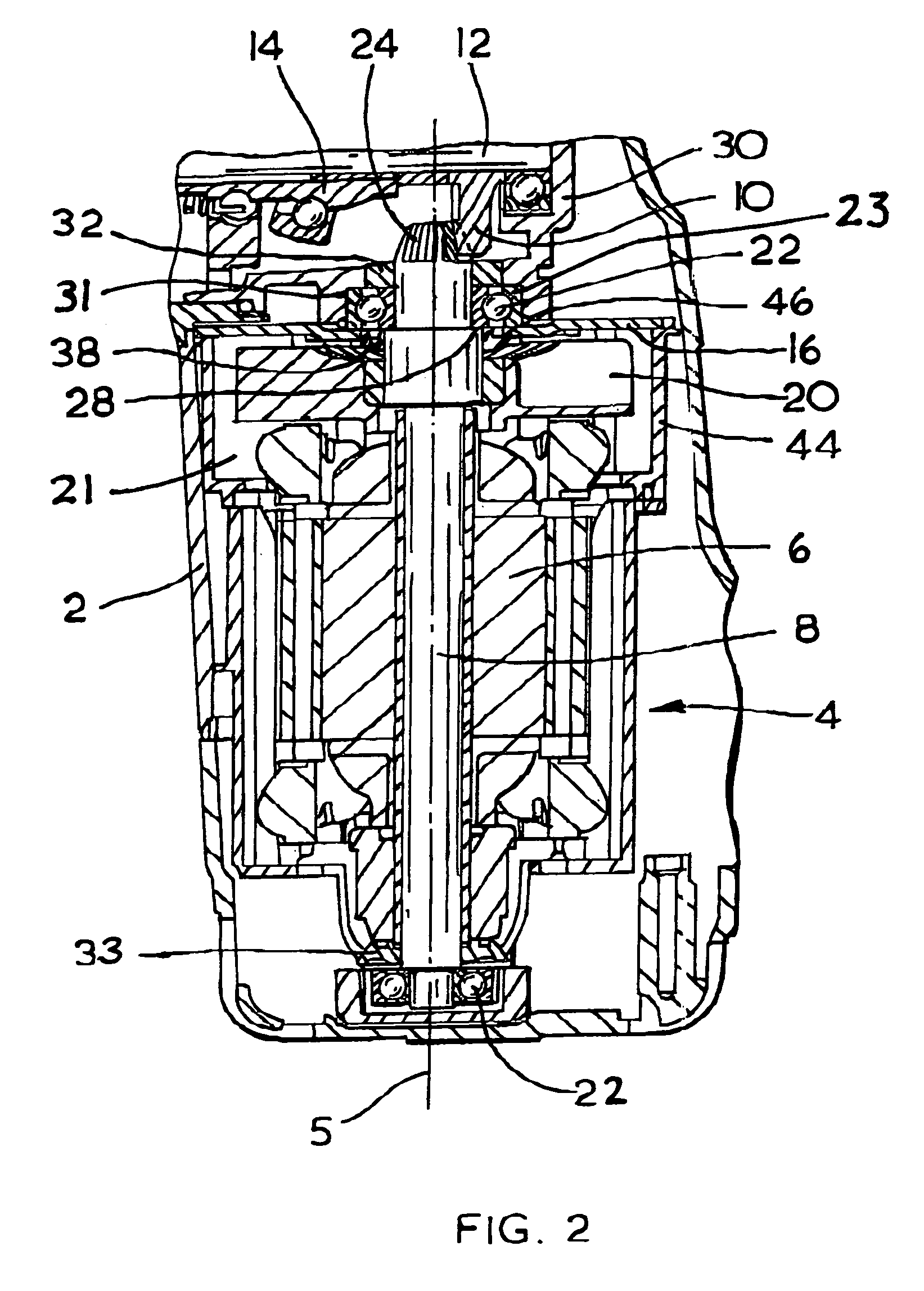
[0023]The hand held electrically powered hammer shown in FIGS. 1 to 3 has a housing comprising a motor housing portion (2) within which an electric motor (4) of the hammer is housed. The motor (4) is aligned with its longitudinal axis (5) perpendicular to the longitudinal axis (3) of a spindle (not shown) of the hammer. The present invention is equally applicable to a hammer in which the axis of the longitudinal motor is parallel, or at any other angle, to the longitudinal axis (3) of the spindle of the hammer.

[0024]A tool holder (26) is located at the forward end of the spindle. A tool or bit (not shown) can be non-rotatably and releasably fitted within the tool holder so as to allow limited reciprocation of the tool or bit with respect to the tool holder. The hammer has a rear handle (18) in which an on / off trigger (20) is located for actuating a switch for actuating power supply to the motor (4). The armature shaft (8) of the motor has a pinion (24) at its end closest to the spin...


PUM

PropertyMeasurementUnit
resilientaaaaaaaaaa
angleaaaaaaaaaa
actuating poweraaaaaaaaaa

Abstract

A hand held electrical tool includes a gear casing for housing a drive mechanism, which gear casing comprises an entrance. The tool's motor includes an armature shaft having an end at which a pinion is formed for engaging the drive mechanism. A motor plate having a central opening fixes the gear casing with respect to the motor and is mounted around the armature shaft adjacent said pinion end and a shaft bearing is located between the motor plate and the pinion. The pinion and bearing are received in the entrance to the gear casing. A moulded on resilient sealing ring is located around the central opinion through the motor plate for sealing between the motor plate and the armature shaft and a moulded on resilient O-ring is located on the face of the motor plate facing the bearing for engaging the outer race of said bearing.

Description

[0001]The present invention relates to hand held tools powered by an electric motor, and in particular to a motor mounting and sealing arrangement for drilling and / or hammering tools.BACKGROUND OF THE INVENTION[0002]In such tools an electric motor may be used for providing a rotary drive to a spindle drive mechanism for rotatingly driving a tool and / or bit of the tool and / or for providing a reciprocating drive to a hammer drive mechanism for providing repeated impacts to the tool and / or bit. The motor may be assembled as a motor sub-assembly in a housing portion, with for example, a motor cooling fan. The motor sub-assembly may then be fixed with respect to a gear casing portion of the tool which may house the spindle drive mechanism and / or hammer drive mechanism of the tool. The arrangement for fixing the motor with respect to the gear casing will need to be robust, should enable efficient rotary drive transmission between an armature shaft of the motor to the drive mechanisms of t...

Claims


Application Information

Patent Timeline
Patent Type & Authority Patents(United States)
IPC IPC(8): E21B4/04E21B6/02B23B45/16B25D17/00B25F5/00F16J15/32
CPCB25D17/00F16J15/3252B25F5/001B25D2216/0023B25D2250/365B25D2250/121
Inventor SOIKA, MARTINHERTING, RAINER
Owner BLACK & DECKER INC
Why Eureka
Try Eureka