
Stop position estimating apparatus of internal combustion engine

a technology of estimating apparatus and internal combustion engine, which is applied in the direction of machines/engines, propulsion parts, and propulsion using engine-driven generators, etc., can solve the problems of complicated logic of estimating processing, and achieve accurate estimating of engine stop position

Active Publication Date: 2006-07-18
TOYOTA JIDOSHA KK
View PDF14 Cites 33 Cited by
  • Summary
  • Abstract
  • Description
  • Claims
  • Application Information

AI Technical Summary

Benefits of technology

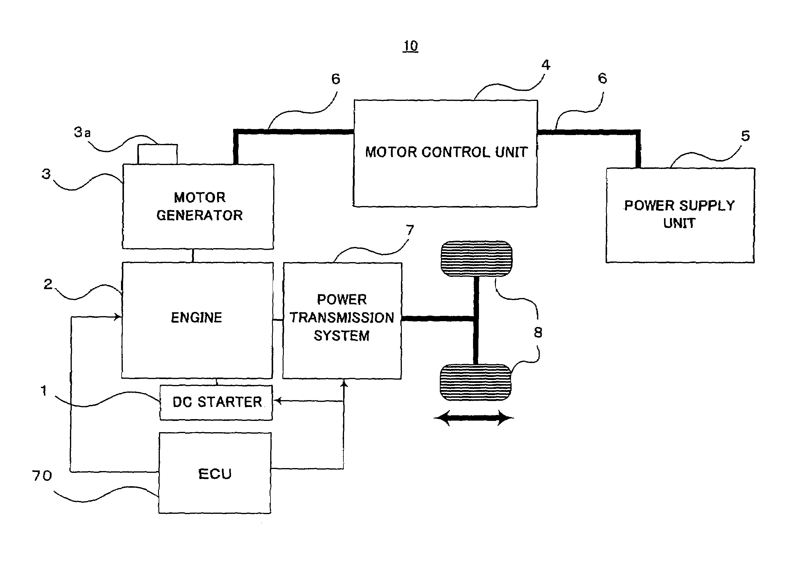
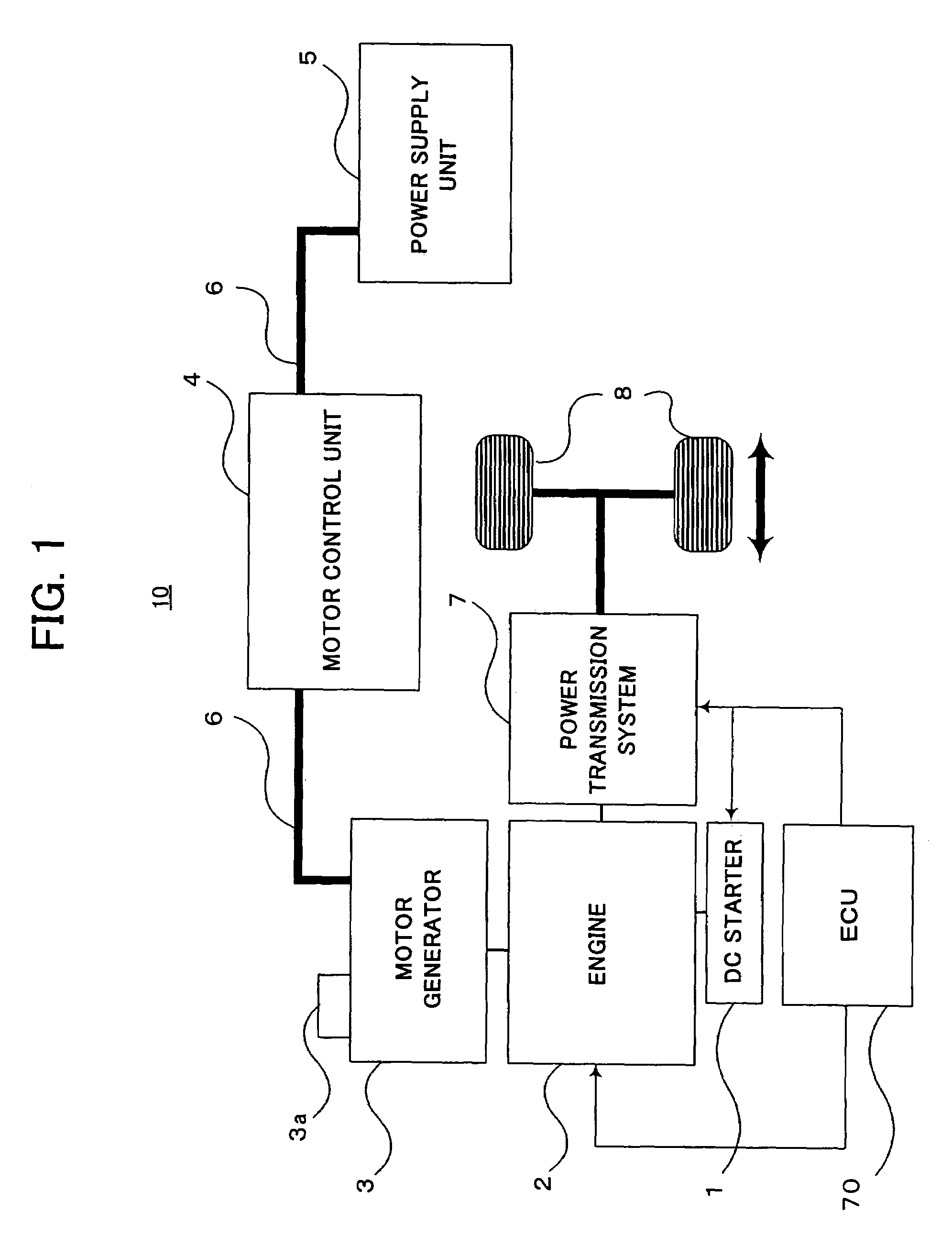
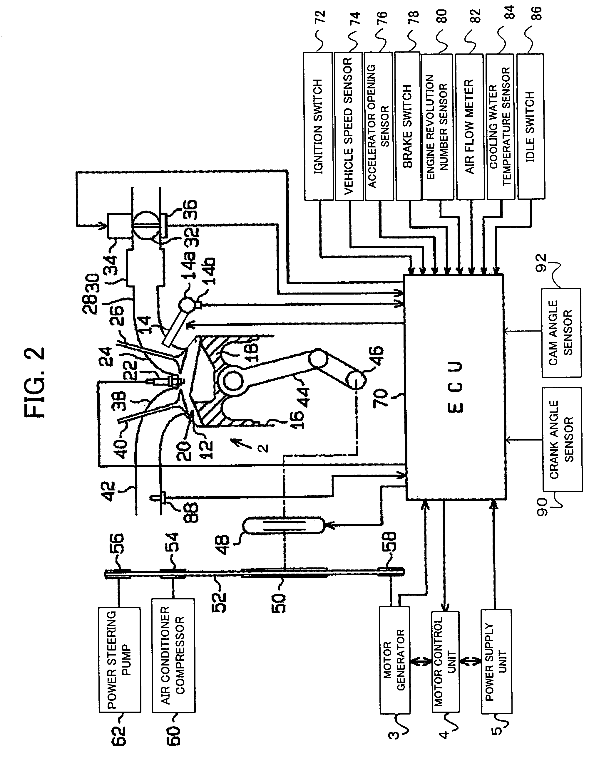
The present invention provides a stop position estimating apparatus for an internal combustion engine that can accurately estimate the engine's stop position without requiring complicated arithmetic operation processing. The apparatus includes a motor generator interlocked with the engine's crankshaft, a first detecting unit for detecting the rotation position of the motor generator, and a second detecting unit for detecting the crank angle of the engine. By utilizing the detected rotation position of the motor generator and the crank angle detected by the second detecting unit, the apparatus can accurately estimate the stop position of the engine. Additionally, the apparatus may include a rotation direction detecting unit for detecting the rotation direction of the engine, and a correcting unit for correcting the estimated crank angle based on the rotation direction and the crank angle detected by the second detecting unit. The apparatus may also include a unit for detecting the number of revolution of the engine, and the correction unit may correct the estimated crank angle only when the number of revolution is within a predetermined range to improve accuracy.

Problems solved by technology

However, the method for estimating the engine stop position by utilizing only the output of the crank angle sensor, as exemplified in the above-mentioned Document-1, has the problem that the logic of the estimating processing is complicated.

Method used


Image

  • Stop position estimating apparatus of internal combustion engine
  • Stop position estimating apparatus of internal combustion engine
  • Stop position estimating apparatus of internal combustion engine

Examples


first example

[0108]Next, a first example of the present invention will be explained. The first example is to perform crank angle estimation with high accuracy by combining the outputs of the motor angle sensor at the side of the motor generator and the crank angle sensor and the cam angle sensor at the side of the engine.

[0109]As shown in Table in FIG. 8, it is the MG position signal that can detect the crank angle with the highest accuracy. However, the absolute crank angle cannot be obtained from the MG position signal. Consequently, the crank angle is calculated by the MG position signal having the highest accuracy, and correction is performed by using the TDC signal or the NE signal which shows the absolute crank position, whereby the crank angle is estimated with high accuracy.

[0110]FIG. 10 shows the concrete example. With the MG position signal, the crank angle can be detected with the resolution of 3° CA as described above. Accordingly, the crank angle is basically calculated based on the...

second example

[0119]Next, a second example of the present invention will be explained. The second example is to perform the correction of the MG estimate crank angle in the crank angle estimating processing shown in the first example only when the number of engine revolution is within the predetermined range.

[0120]As described above, in the first example, the MG estimate crank angle is calculated based on the MG position signal to estimate the crank angle with high accuracy, and the MG estimate crank angle thus calculated is corrected according to the TDC signal and the like. However, in the state that the number of engine revolution is high (for example, 4,000 rpm or more), the arithmetic operation load of estimating the MG estimate crank angle and its correction processing becomes excessively large. On the other hand, when the number of engine revolution is too low, the reliability of the output signal from the crank angle sensor is low. The accuracy of output of an ordinary crank angle sensor ...

third example

[0123]Next, a third example of the present invention will be explained. In the third example, in the crank angle estimating processing in the first example, the error when the MG estimate crank angle is corrected is recorded, and a standard error range is determined. When a large error exceeding the standard error range is detected, it is determined to be caused by a temporary factor such as a noise, for example, and correction is not performed. As for the errors included in the MG estimate crank angle, an error caused by the slip of the belt 52 connecting the MG pulley 58 and the crankshaft pulley 50, and an arithmetic operation error when the MG estimate crank angle is calculated based on the MG position signal are basically conceivable. However, it is considered that the error due to the slip of the belt stays within a certain range in accordance with the structure of the belt and the pulley portions, and that the arithmetic operation error of the MG estimate crank angle also sta...


PUM


Abstract

A stop position control apparatus of an internal combustion engine is applied to a vehicle having of a motor or a generator connected to a crankshaft of the engine, such as an economic-running vehicle and a hybrid vehicle. A rotation position of a motor generator is detected by a motor angle sensor, and a crank angle of the engine is detected by a crank angle sensor. A stop position of the internal combustion engine, at the time of stoppage is estimated based on the rotation position of the motor generator and the crank angle. By utilizing the results, the stop position of the internal combustion engine can be accurately estimated. By detecting a rotation direction of the crankshaft, the stop position of the engine can be accurately estimated even when the engine is rotated in the reverse direction at the time of the engine stopping.

Description

BACKGROUND OF THE INVENTION[0001]1. Field of the Invention[0002]The present invention relates to a stop control of an internal combustion engine, and particularly relates to a stop position estimating apparatus for estimating a stop position of an internal combustion engine.[0003]2. Description of Related Art[0004]Recently, there is known an engine stop and start control apparatus for automatically stopping an internal combustion engine (hereinafter, also referred to as “engine”) when the vehicle stops and for automatically restarting the engine to start the vehicle when an instruction to start is given in the stopped state, in order to reduce a fuel consumption amount and exhaust gas during idling, from the viewpoint of environmental conservation, resources and energy saving or the like. This control is also called “idling stop” or the like.[0005]It is known that, when the idling stop is automatically carried out, it is effective to control the stop position of the engine in order ...

Claims


Application Information

Patent Timeline
Patent Type & Authority Patents(United States)
IPC IPC(8): G06G7/70B60K25/02B60W10/08F02D17/00F02D29/02F02D41/04F02D41/34F02D45/00F02N11/04
CPCB60K6/485B60L11/1872B60W10/08F02D41/042F02D41/009B60L2240/441B60W2510/0638Y02T10/705F02D2041/0095F02N11/04Y02T10/6226Y02T10/7005B60K2006/268B60L15/20B60L2240/44B60L2260/44B60L50/16F02N19/005F02N2019/008Y02T10/62Y02T10/64Y02T10/7072Y02T10/72Y02T10/70
Inventor KATAOKA, KENJIKUSAKA, YASUSHI
Owner TOYOTA JIDOSHA KK
Learn More