Butterfly valve for controlling a gas pressure

a technology of butterfly valve and gas pressure, which is applied in the direction of valve details, lift valves, air-treatment apparatus arrangements, etc., can solve the problems of vibration, wear and noise, and adverse tension in the closure member of butterfly valve, and achieve the effect of restricting the cross-sectional area

Inactive Publication Date: 2006-07-18
NORD MICRO GMBH & CO OHG
View PDF9 Cites 10 Cited by
  • Summary
  • Abstract
  • Description
  • Claims
  • Application Information

AI Technical Summary

Benefits of technology

[0004]The object of the present invention is to provide a butterfly valve which ensures a restricted cross-sectional area of the valve housing even if a breaking of the closure member occurs.

Problems solved by technology

Since air is a compressible fluid, a butterfly valve controlling the air pressure is subject to undesired effects such as vibrations, wear and noise.
For example, a high pressure or a high speed flow rate of the air generates aerodynamic throttling over a wide range of opening positions resulting in an adverse state of tension in the closure member.
This state of tension may effect damages of the closure member such as a crack.
A spreading crack may have the consequences of breaking the closure member and, thereby, releasing a cross-sectional area of the valve housing which leads to a sudden and dangerous loss of pressure.

Method used


Image

  • Butterfly valve for controlling a gas pressure
  • Butterfly valve for controlling a gas pressure
  • Butterfly valve for controlling a gas pressure

Examples


Embodiment Construction

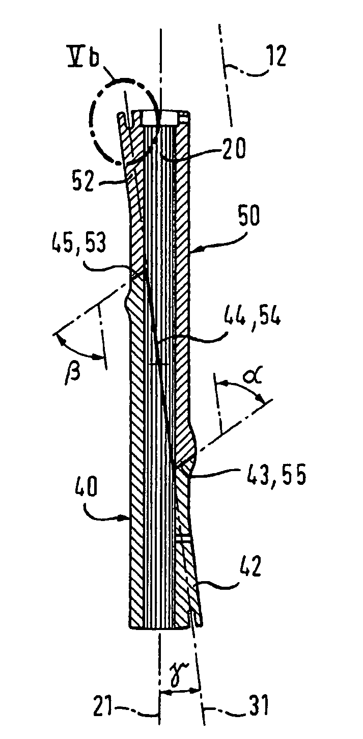
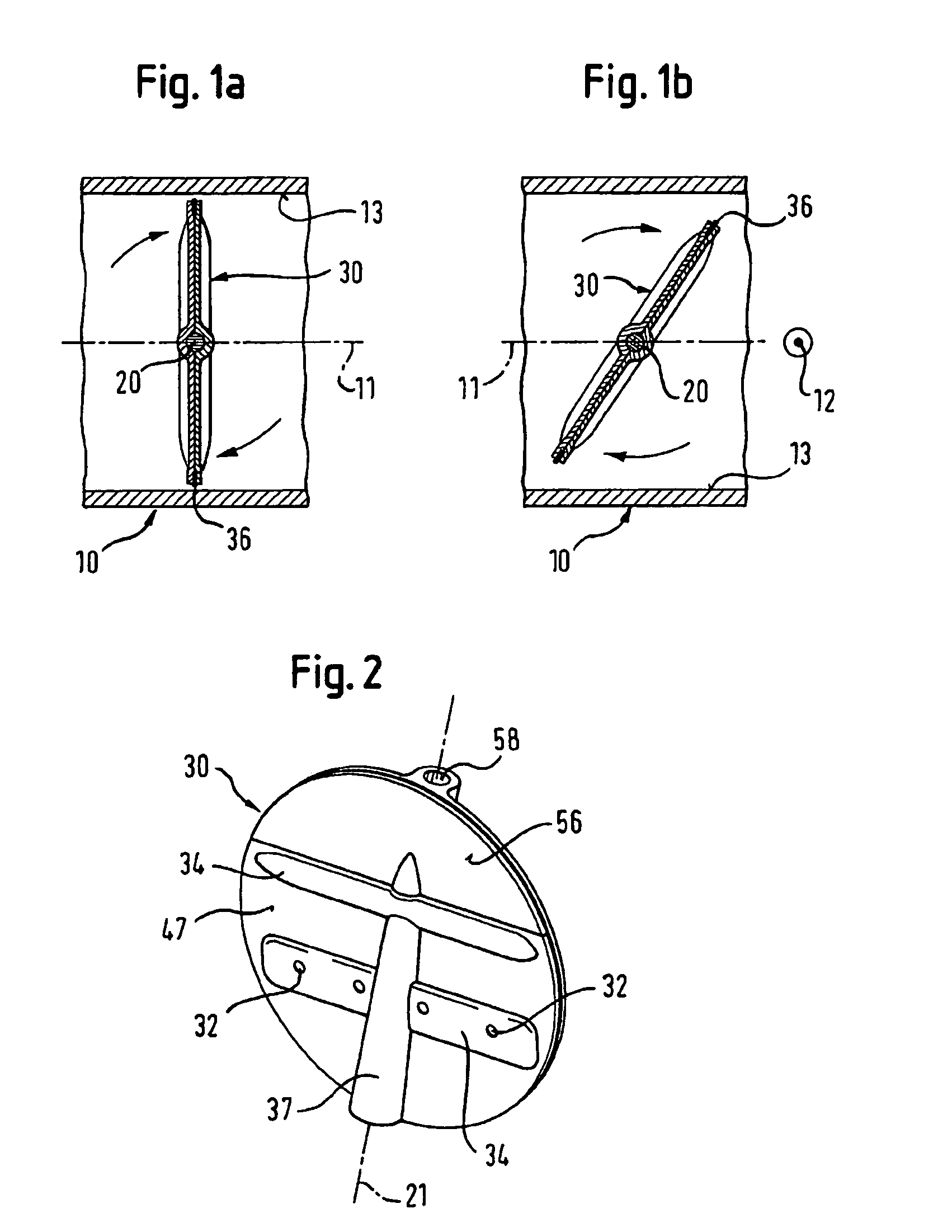
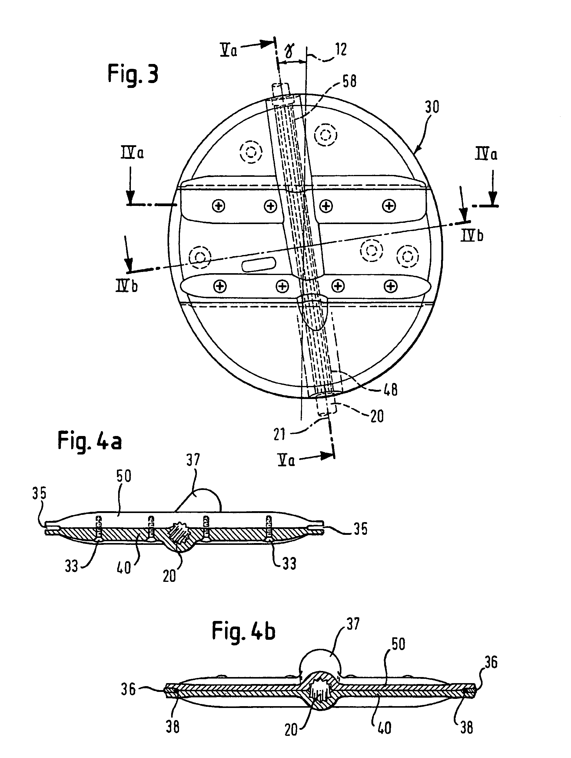
[0030]The butterfly valve as shown in FIGS. 1a and 1b comprises a valve housing 10 which has a longitudinal axis 11 and defines a flow path along the longitudinal axis 11 for air flowing out of the cabin of an aircraft. The butterfly valve further comprises a closure member 30 or flap which is pivotally mounted in the valve housing 10 and connected to a shaft 20 having a rotation axis 21 and driven by an actuator, for example an electric motor. In this way, the closure member 30 is pivotable between an open position showing in FIG. 1b, which allows the air to flow through the valve housing 10, and a closed position showing in FIG. 1a, which prevents the air from flowing through the valve housing 10.

[0031]Commercial aircrafts are equipped with such a butterfly valve for controlling the air pressure inside the cabin. During the flight of an aircraft, variations in aircraft altitude cause rapid changes in ambient pressure. The butterfly valve typically controlled by a cabin pressure co...


PUM


Abstract

A butterfly valve for controlling a gas pressure, in particular inside a cabin of an aircraft, comprises a valve housing (10) having a longitudinal axis (11), a shaft (20) having a rotation axis (21), and a closure member (30) connected to the shaft (20). The closure member (30) is pivotally mounted in the valve housing (10) for rotation about the rotation axis (21) between an open position and a closed position. Moreover, the closure member (30) consists of a first disk (40) and a complementary second disk (50) which abut against each other. The first disk (40) and the second disk (50) are symmetrically arranged with regard to a symmetric axis (31) extending at a predetermined angle of inclination to the rotation axis (21). Such a butterfly valve ensures a restricted cross-sectional area of the valve housing (10), even if breaking of the closure member (30) occurs.

Description

BACKGROUND OF THE INVENTION[0001]The present invention generally relates to a butterfly valve controlling a gas pressure and more particularly to a butterfly valve for controlling a gas pressure inside the cabin of an aircraft.[0002]Butterfly valves are normally used for controlling the flow rate of a liquid or gaseous fluid. Conventional butterfly valves comprise to this end a closure member positioned in a valve housing for rotation about a rotation axis defined by a shaft. Typically, the closure member is configured as a disk which is rotated by the shaft between an open position allowing the fluid to flow through the valve housing and a closed position preventing the fluid from flowing through the valve housing. The shaft is driven by a torque usually applied by an external actuator, such as an electric motor.[0003]Especially in the aviation industry, butterfly valves are employed for controlling the air pressure inside the cabin of an aircraft, as disclosed in U.S. Pat. No. 5,8...

Claims


Application Information

Patent Timeline
Patent Type & Authority Patents(United States)
IPC IPC(8): F16K1/22B64D13/02
CPCB64D13/02F16K1/222F16K1/22
Inventor DREISILKER, RALFPETRI, BERNHARD
Owner NORD MICRO GMBH & CO OHG
Why Eureka
Try Eureka