
Elevator installation with a buffer for creating a zone of protection in an elevator installation and a method of creating a zone of protection

Inactive Publication Date: 2006-07-18
INVENTIO AG
View PDF13 Cites 18 Cited by
  • Summary
  • Abstract
  • Description
  • Claims
  • Application Information

AI Technical Summary

Benefits of technology

[0011]The present invention has the object of providing a solution which makes it possible to create a zone of protection at the lower or at the upper end of an elevator shaft in the case of need.
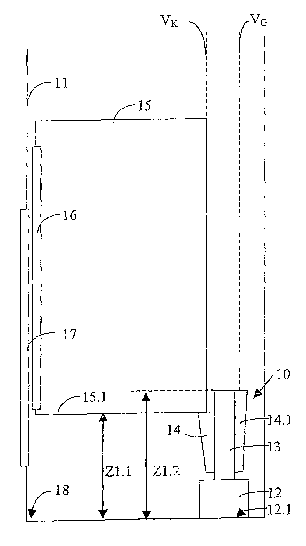
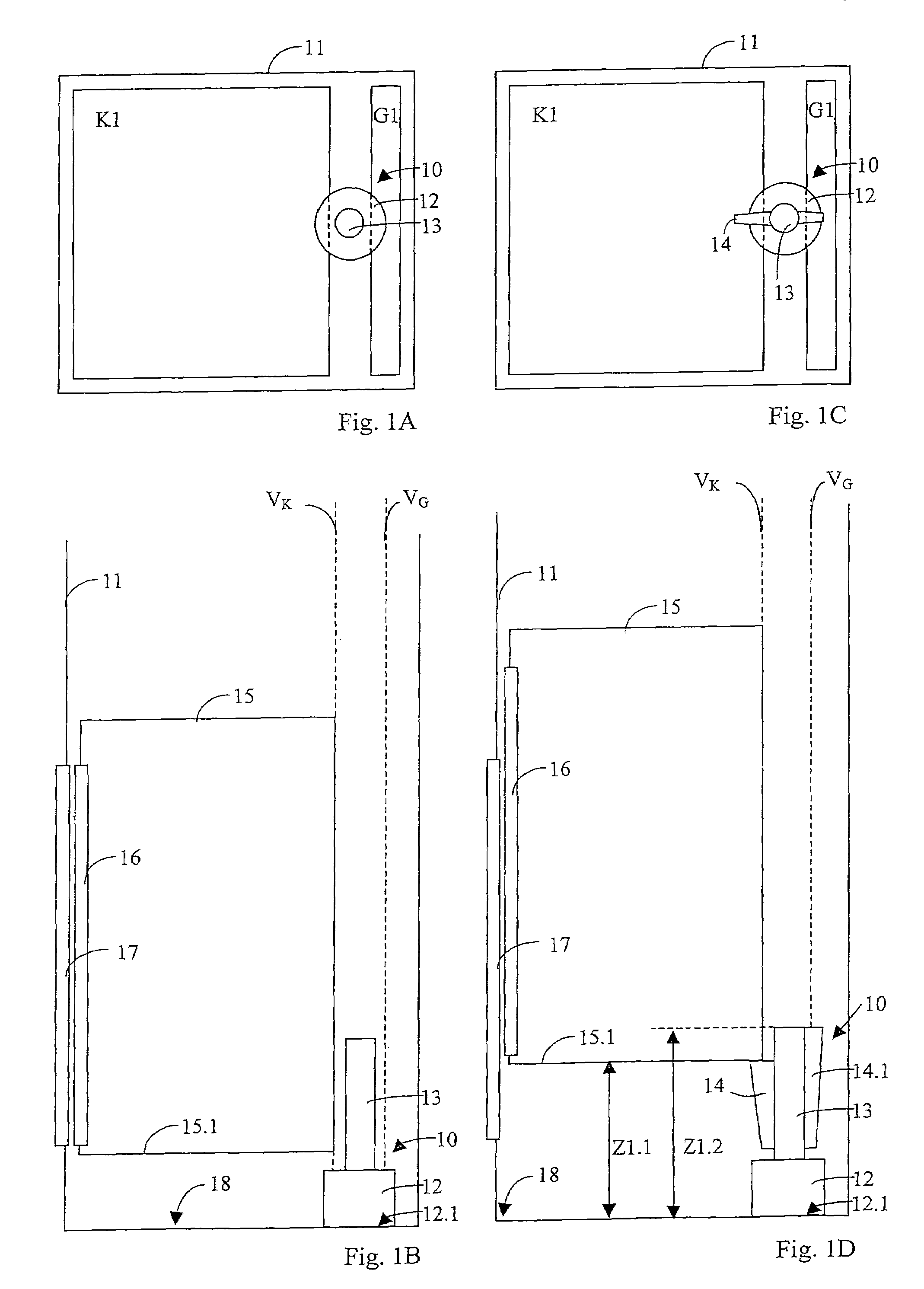
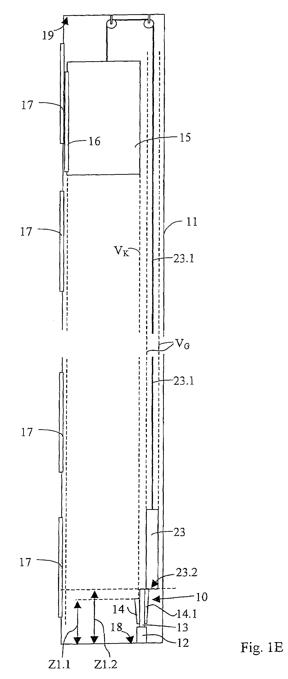
[0014]Consequently, the movable means can be brought into a use setting in which they are arranged in such a manner that the elevator car and / or the counterweight can be brought into a mechanical contact with the movable means. It is thereby made possible to be able to selectably support the elevator car or the counterweight in a first or a second predetermined spacing above a floor by a single buffer. The predetermined first spacing and the predetermined second spacing can be different depending on the respective arrangement and form of the buffer or the movable means. The elevator car and the counterweight can accordingly be supported at different heights.
[0018]The buffer can be developed in such a manner that a damping element projects into the paths of the elevator car and the counterweight when the movable means are brought into the normal setting. Thus, solely through selection of the arrangement of a single buffer the elevator car can be prevented from overrunning a lowermost stopping position in the downward direction and an uppermost stopping position in the upward direction.

Problems solved by technology

Due to the fact that such buffers have to be arranged at the shaft floor or shaft head directly below or above the elevator car, a specific space requirement results.
In the case of elevator installations without a shaft pit, such a standard arrangement of a buffer is not possible, since little space is present underneath the elevator car.
There is frequently too little space due to constructional or other reasons for a conventional elevator installation with a shaft pit and a shaft head.
It is a disadvantage of this form of embodiment that it is indeed suitable for creating a zone of protection at the shaft floor, but does not offer any possibility of stopping overrunning of the lowermost stopping position of the elevator car in the elevator shaft in the downward direction after transiting a predetermined travel path.
It is a disadvantage of this form of embodiment that for creating a zone of protection at the shaft head there is needed a device which is seated on the elevator car.

Method used


Image

  • Elevator installation with a buffer for creating a zone of protection in an elevator installation and a method of creating a zone of protection
  • Elevator installation with a buffer for creating a zone of protection in an elevator installation and a method of creating a zone of protection
  • Elevator installation with a buffer for creating a zone of protection in an elevator installation and a method of creating a zone of protection

Examples


second embodiment

[0052]FIGS. 2A to 2D show—as the present invention—an elevator installation with a buffer 30 in different schematic views and in different states. The illustrated buffer 30 is a buffer for supporting an elevator car 35 above a floor 38 of an elevator shaft 31. The buffer serves as an overrun protection and as means for creation of a temporary zone of protection. The elevator car 35 is so connected with a counterweight that the elevator car 35 is movable upwardly and downwardly along a path VK, and the counterweight upwardly and downwardly along a path VG, in the elevator shaft 31. The counterweight, a support means for the elevator car 35 and the counterweight, a drive pulley, guide rails and other usual elements of an elevator installation are not shown in FIGS. 2A to 2D. The buffer 30 has a longitudinal extent substantially parallel to the paths VK and VG of the elevator car 35 and the counterweight. The buffer 30 is so constructed and arranged that it projects at least partly int...

third embodiment

[0063]FIGS. 3A to 3D show—as the present invention—an elevator installation with a buffer 40 in different schematic views and in different states. The illustrated buffer 40 is a buffer for supporting an elevator car 45 above a floor 48 of an elevator shaft 41. The buffer serves as overrun protection and as means for creating a temporary zone of protection in an elevator installation without a pit, i.e. in an elevator installation in which the lowermost stopping level of the elevator car lies at such a short distance above the floor that no space for a shaft pit is present. The elevator car 45 is so connected with a counterweight that the elevator car 45 and the counterweight are movable upwardly and downwardly along paths in the elevator shaft 41. The counterweight, a support means for the elevator car 45 and the counterweight, a drive pulley, guide rails and other usual elements of an elevator installation are not shown in FIGS. 3A to 3D. The buffer 40 has a longitudinal extent sub...


PUM


Abstract

A buffer creates at least one zone of protection in an elevator installation including an elevator car and a counterweight movable along respective paths in an elevator shaft. The buffer has a movable portion movable into the path of the elevator car and / or into the path of the counterweight in such a manner that the elevator car or the counterweight can be brought into mechanical contact with the movable portion and each of the elevator car and the counterweight is supported at a predetermined height above a floor of the elevator shaft so that a zone of protection is available below or above the elevator car.

Description

BACKGROUND OF THE INVENTION[0001]The present invention is an elevator installation with a buffer for creating a zone of protection. A method of creating a zone of protection is a further subject of the invention.[0002]Elevator installations are usually provided with one or more buffers which are arranged at the shaft floor of an elevator shaft in order to stop the elevator car when overrunning the lowermost stopping position in the elevator shaft in the downward direction and / or when overrunning the uppermost stopping position in the elevator shaft in the upward direction after transit of a predetermined travel path. This buffer is usually seated below the elevator car and / or the counterweight.[0003]In order to prevent overrunning of an uppermost stopping position in the elevator shaft in the upward direction at the latest after transiting a predetermined travel path, buffers can also be arranged at the shaft head above the elevator car. Due to the fact that such buffers have to be ...

Claims


Application Information

Patent Timeline
IPC IPC(8): B66B5/28B66B5/16B66B5/00
CPCB66B5/288B66B5/005
Inventor HUBER, MARCELKOCHER, JOHANNES
Owner INVENTIO AG
Learn More