
Variable valve control system and method for multi-cylinder internal combustion engine

a control system and multi-cylinder technology, applied in the direction of electrical control, process and machine control, instruments, etc., can solve the problems of unstable combustion state, difficult to secure combustion stability and responsive characteristics, etc., to prevent excessive reduction of intake air quantity.

Inactive Publication Date: 2006-07-18
NISSAN MOTOR CO LTD
View PDF7 Cites 12 Cited by
  • Summary
  • Abstract
  • Description
  • Claims
  • Application Information

AI Technical Summary

Benefits of technology

[0007]It is, therefore, an object of the present invention to provide variable valve control system and method for a vehicular multi-cylinder internal combustion engine which are capable of preventing the excessive reduction of the intake air quantity when the reference position is correctively learned without a limitation of the control range of the lift characteristic.

Problems solved by technology

Hence, if a rotational position of the control shaft were the mechanical minimum position to correctively learn the sensor output during an actual engine operation, an intake air quantity might become excessively decreased and a combustion state might become unstable.
In addition, even during a fuel supply cut-off as disclosed in the above-described Japanese Patent Application First Publication, it becomes difficult to secure combustion stability and responsive characteristic during a fuel recovery at which a fuel supply (fuel injection) to the engine is resumed.
Furthermore, if, in a multi-cylinder internal combustion engine having a plurality of cylinder groups such as a V-shaped engine, the lift characteristics are wholly and simultaneously set to minimum at one time in order to carry out the corrective learning for the plurality of cylinder groups, the intake air quantity becomes easy to be excessively small.
In this case, it is not desirable since a control range for the lift characteristic is limited.

Method used


Image

  • Variable valve control system and method for multi-cylinder internal combustion engine
  • Variable valve control system and method for multi-cylinder internal combustion engine
  • Variable valve control system and method for multi-cylinder internal combustion engine

Examples


Embodiment Construction

[0015]Reference will hereinafter be made to the drawings in order to facilitate a better understanding of the present invention.

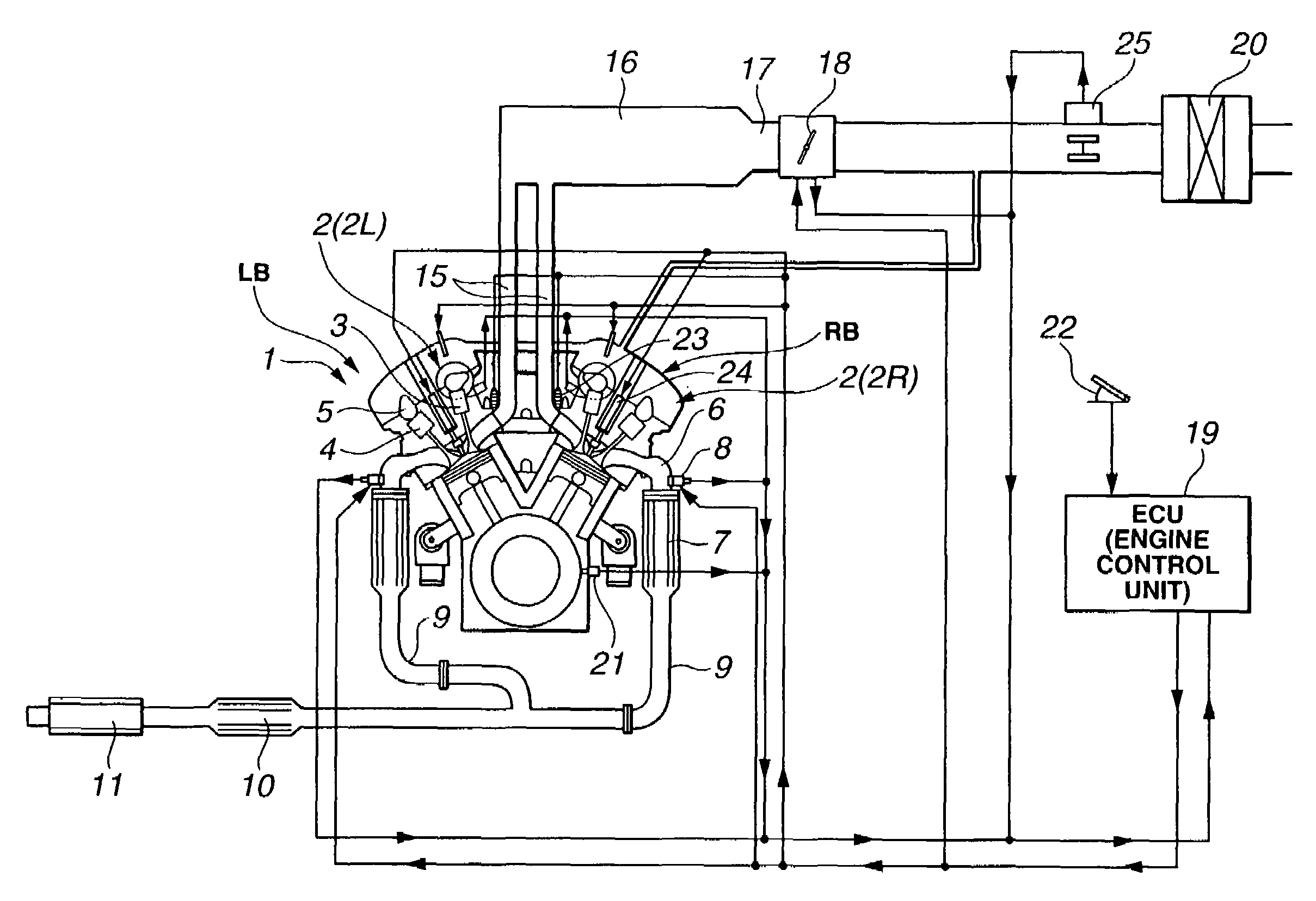
[0016]A preferred embodiment of a variable valve control system according to the present invention which is applicable to intake valves of a vehicular spark ignited gasoline internal combustion engine will be described below. FIG. 1 shows the embodiment of the variable valve control system according to the present invention which is applicable to a V-shaped six-cylinder gasoline internal combustion engine.

[0017]In FIG. 1, a variably operated valve mechanism 2 (2R, 2L) as will be described later is installed on an intake valve 3 of each of left and right banks RB, LB. It is noted that an operated mechanism on an exhaust valve 4 is a direct drive type which drives exhaust valve 4 by means of an exhaust camshaft 5 and its valve lift characteristic is always constant.

[0018]An exhaust manifold 6 of each of left and right banks LB, RB is connected to a catalytic ...


PUM


Abstract

In variable valve control system and method for a vehicular multi-cylinder internal combustion engine, a first learning timing at which a reference position of a lift characteristic is learned for a first cylinder group is deviated from a second learning timing at which the reference position is learned for a second cylinder group.

Description

BACKGROUND OF THE INVENTION[0001]1. Field of the Invention[0002]The present invention relates to variable valve control system and method for a (vehicular) multi-cylinder internal combustion engine in which a variably operated valve mechanism which continuously varies a lift characteristic of an intake valve or an exhaust valve is equipped for each of a plurality of cylinder groups and, particularly, relates to a technique of a correction or learning (corrective learning) process of a reference position of the above-described lift characteristic.[0003]2. Description of the Related Art[0004]In an internal combustion engine, particularly, in a gasoline internal combustion engine which develops an output in accordance with an intake air quantity, a variably operated valve mechanism which varies a lift characteristic of an intake valve in accordance with an engine driving condition has been used in order to improve a fuel consumption. A Japanese Patent Application First Publication No. ...

Claims


Application Information

Patent Timeline
Patent Type & Authority Patents(United States)
IPC IPC(8): F01L1/34F01L13/00F02D13/00F02D13/02F02D41/00F02D41/12F02D41/24F02D41/34
CPCF01L13/0015F02D13/0207F02D41/2438F02D41/2441F02D41/2464F02D41/0082F01L1/34F01L2013/0073F01L2800/00F01L2820/032Y02T10/18F02D41/123F02D2041/001Y02T10/12
Inventor ARAI, MASAHIROKAWAMURA, KATSUHIKO
Owner NISSAN MOTOR CO LTD
Learn More