Power controlling apparatus with power converting circuit
a technology of power converting circuit and power control apparatus, which is applied in the direction of electric generator control, dynamo-electric converter control, instruments, etc., can solve the problems that the power generation operation accompanying great power cannot be continued for a long period, and the loss of diodes is remarkabl
- Summary
- Abstract
- Description
- Claims
- Application Information
AI Technical Summary
Benefits of technology
Problems solved by technology
Method used
Image
Examples
embodiment 1
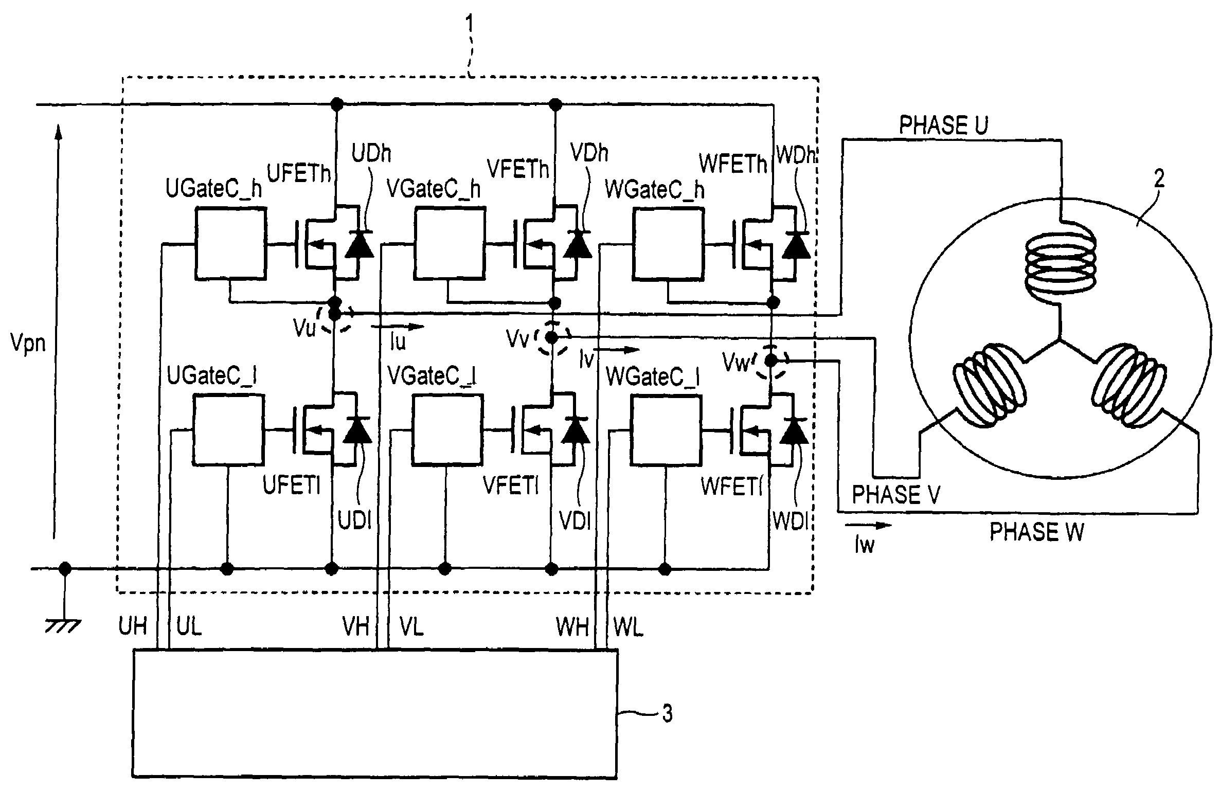
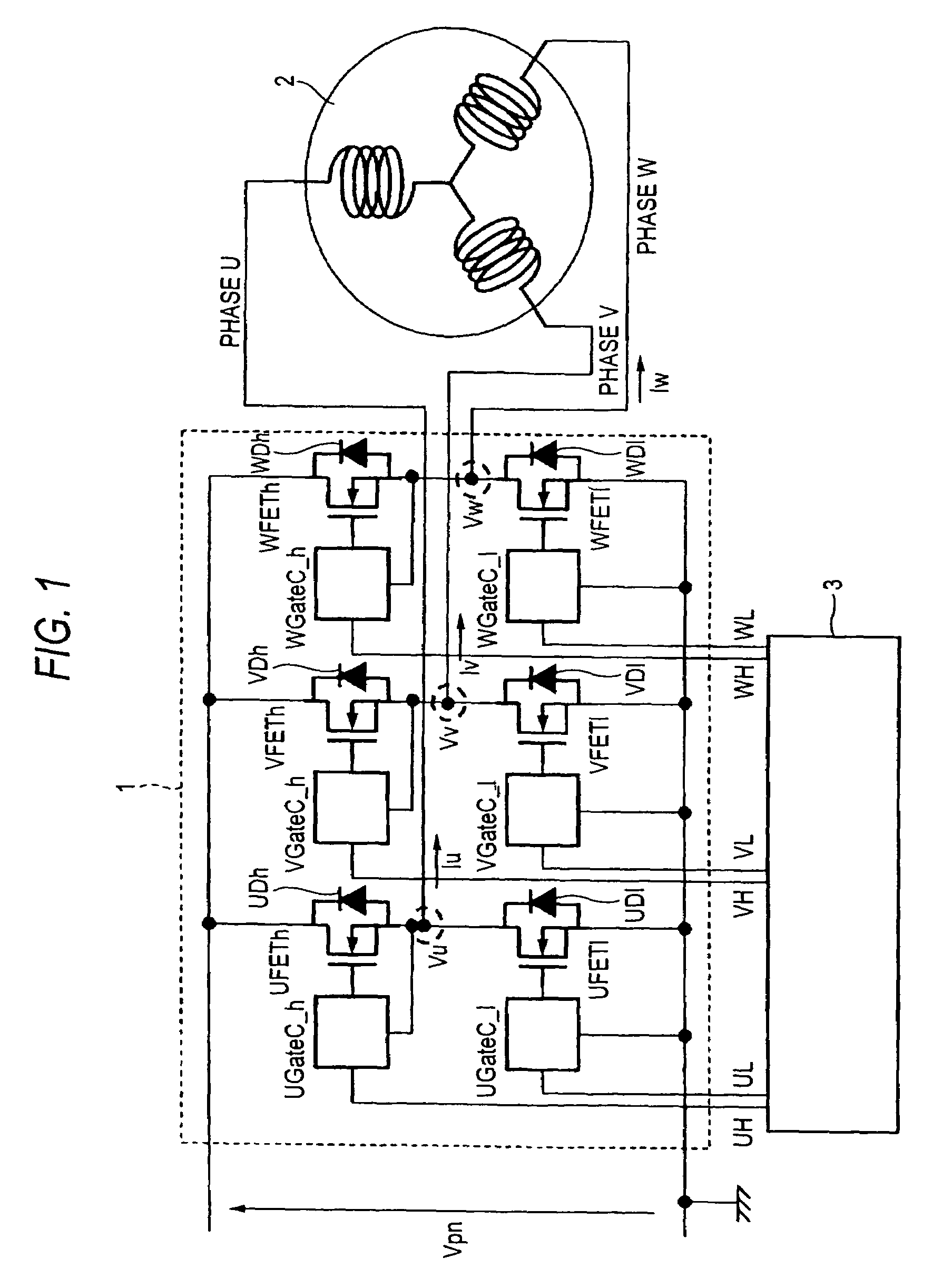
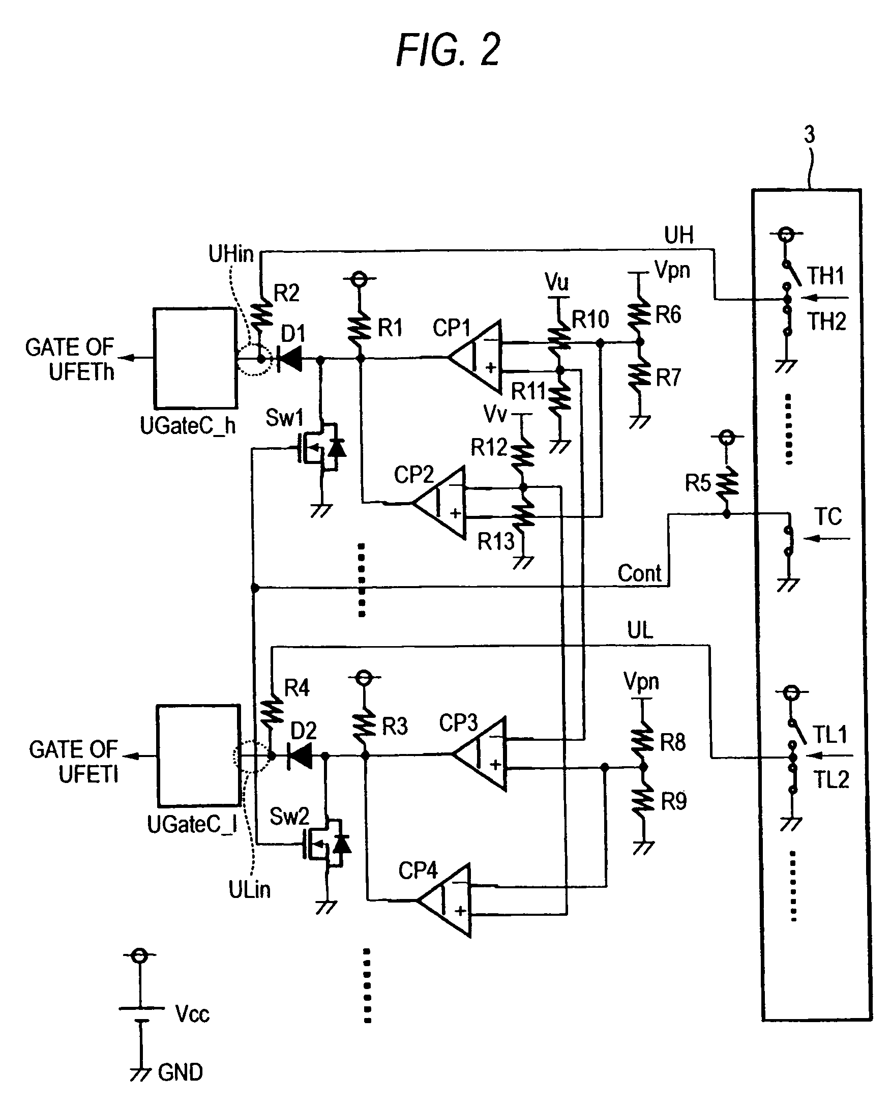
[0029]FIG. 1 shows the entire configuration of a power controlling apparatus according to Embodiment 1 of the invention. A three-phase power converting circuit 1 carries out a bidirectional power converting operation by a controlling circuit 3. Reference symbol Vpn denotes the DC voltage of a DC power source. The terminals are connected to an energy accumulation source such as a battery. A motor / generator 2, which is a power generation motor, shifts power from the energy accumulation source to the motor / generator 2 by carrying out an inverter operation of the power converting circuit 1, and the motor / generator 2 generates a rotational drive force to rotate axles, etc., (motor drive operation). Also, the motor / generator 2 is rotated by power given by the outside, wherein three-phase AC power is generated, and the generated AC power is rectified by the power converting circuit 1 and is charged into the energy accumulation source of a battery, etc.
(Power Generation Operation).
[0030]The...
embodiment 2
[0053]In the preceding Embodiment 1, although a description was given of a circuit configuration in the case where the input of the driver circuit is HIGH ACTIVE (HIGH voltage, and HIGH voltage is supplied to the gate of the power MOSFET). In Embodiment 2, a description is given of a circuit configuration in the case where the input of the driver circuit is LOW ACTIVE (with LOW voltage, and HIGH voltage is supplied to the gate of the power MOSFET). FIG. 5 shows a high-potential side of U-phase. Even if the input to the driver circuit is LOW ACTIVE, it is a matter of course that the low-potential side and other phases have the same construction.
[0054]Connections of the comparators CP1 and CP2 and resistors R5, R6, R7, R10, R11, R12 and R13 are the same as those in Embodiment 1. Output terminals of the comparators CP1 and CP2 are connected to the gates of the power source Vcc and switch Sw103 via a resistor R101. The source of the switch Sw103 is connected to the GND, and the drain th...
embodiment 3
[0058]In the above-described Embodiments 1 and 2, a description was given of that, in the continuity period of the diode, the ON period of the power MOSFET is a ratio of two-thirds the entire continuity period of the diode. If the ON-period is made longer, it is possible to suppress heat generation in the elements. In the present Embodiment 3, a description is given of a circuit configuration and actions for making the ON period longer.
[0059]FIG. 6 shows a construction of Embodiment 3, which shows a construction of only the U-phase high-potential side. The constructions at the low-potential side and in the other phases are the same. Connections of the comparators CP1 and CP2 and resistors R2, R5, R6, R7, R10, R11, R12, and R13, switch Sw1 and diode D1 are the same as those in Embodiment 1.
[0060]The output terminals of the comparators CP1 and CP2 are connected to the power Vcc via a resistor R201, and connected to one input terminal of the NOR circuit IC201 and the resistor R215. The...
PUM
 Abstract
Description
Claims
Application Information
 - R&D
- Intellectual Property
- Life Sciences
- Materials
- Tech Scout
- Unparalleled Data Quality
- Higher Quality Content
- 60% Fewer Hallucinations
Browse by: Latest US Patents, China's latest patents, Technical Efficacy Thesaurus, Application Domain, Technology Topic, Popular Technical Reports.
© 2025 PatSnap. All rights reserved.Legal|Privacy policy|Modern Slavery Act Transparency Statement|Sitemap|About US| Contact US: help@patsnap.com


