
Waterproof relay connector

a relay connector and water-proof technology, applied in the direction of connection insulation, coupling device details, coupling device connections, etc., can solve the problems of not being able to use as a relay connector, too large structure to achieve waterproof ability, and inability to change the arrangement into parallel or series connections, etc., to achieve the effect of easy connection, long connection of lead wires, and waterproof ability

Inactive Publication Date: 2006-07-04
SMK CORP
View PDF12 Cites 19 Cited by
  • Summary
  • Abstract
  • Description
  • Claims
  • Application Information

AI Technical Summary

Benefits of technology

The technical effect of this patent is to provide a waterproof relay connector that is compact, easy to connect and disconnect, and allows for adjustable lead wire length. The connector has a housing with a lead wire insertion hole and a lead wire retaining portion, an elastic portion with a through hole for the lead wire, and a terminal connected to the lead wire. This results in a seal between the through hole of the elastic portion and the lead wire.

Problems solved by technology

However, with this structure in which the lead wire is press-fastened to the terminal, and the resin is filled to provide an integrally-molded construction, when this connector is to used as a waterproof relay connector, for example, between facilities, the connector need to be beforehand mounted on relevant apparatuses since this connector can not be mounted at the field.
Therefore, there was a drawback that when the facilities were to be changed, the arrangement could not be changed into a parallel connection or a series connection.
However, this terminal block is designed to connect the lead wire to facilities, and its structure is too large to be used as a relay connector, and besides has no waterproof ability.
However, an insertion hole for the cable and an insertion hole for the cancellation button have no waterproof ability, and beside this structure is large in size.

Method used


Image

  • Waterproof relay connector
  • Waterproof relay connector
  • Waterproof relay connector

Examples


Embodiment Construction

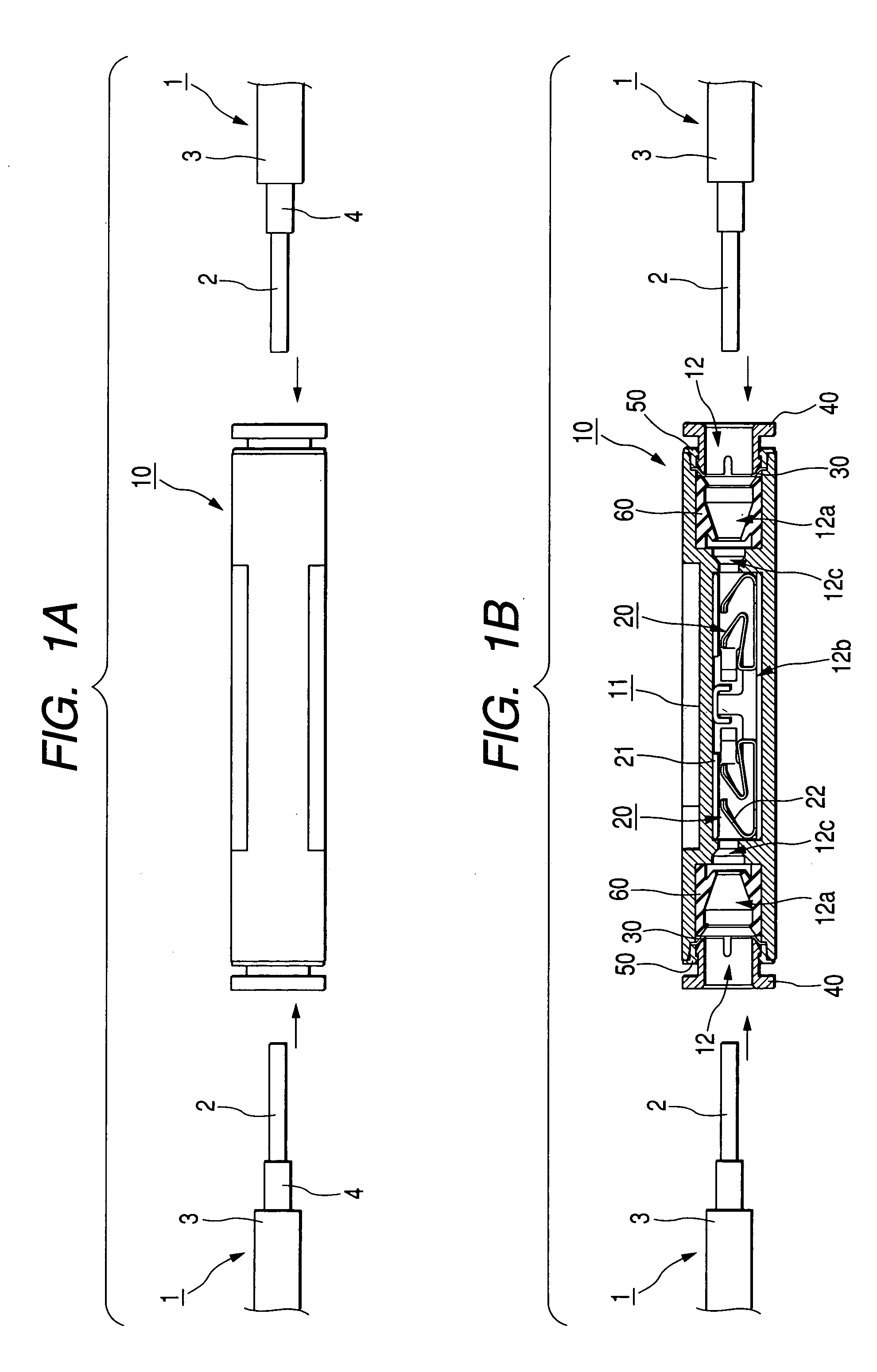
[0032]FIG. 1 shows a preferred embodiment of a waterproof relay connector 10 of the invention.

[0033]FIG. 1A is a side-elevational view of the waterproof relay connector, and FIG. 1B is a cross-sectional view thereof.

[0034]A lead wire 1 comprises an outer covering (commonly referred to as a sheath) 3, and a conductor 2 covered with an inner covering 4 made of an insulator. This invention can be applied to any of single wires having a covering portion.

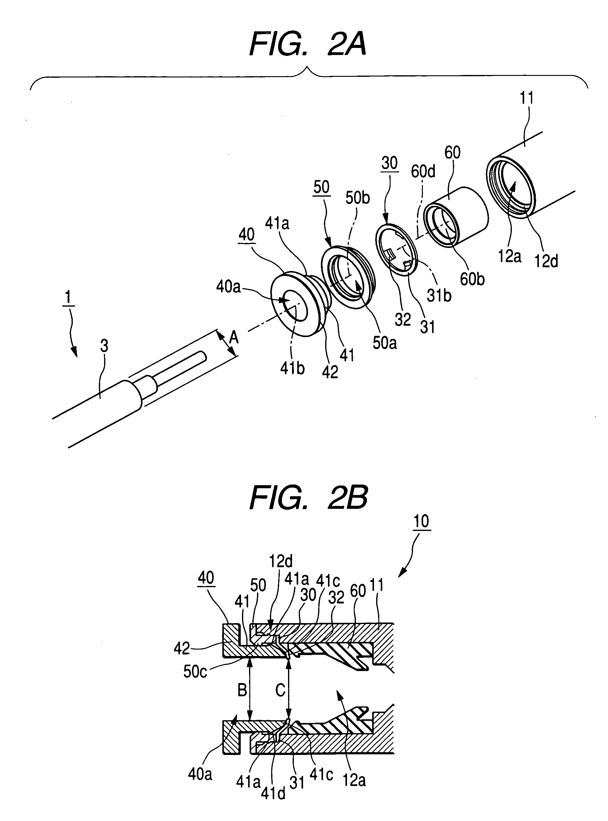
[0035]As shown in FIG. 1B, a lead wire insertion hole 12 is formed in each of front and rear half portions of the waterproof relay connector 10, and a terminal 20, a elastic portion (rubber bushing) 60, a retaining spring member 30, a ring-like retaining member 50 and a push-in member 40 are provided within each lead wire insertion hole 12, and are arranged in this order from an inner end portion of this insertion hole 12.

[0036]A lead wire covering-receiving portion 12a is formed near to an opening portion of the lead wire insertion hole...


PUM


Abstract

The waterproof relay connector for connecting a lead wire includes a connector housing having a lead wire insertion hole, and lead wire retaining means for retaining the lead wire inserted in the lead wire insertion hole, an elastic portion having a through hole extending along the lead wire insertion hole, and a terminal for connection to the lead wire are provided in the connector housing. The lead wire is passed through the through hole in the elastic portion, and a conductor of the lead wire is resiliently connected to the terminal, so that a seal is formed between an inner peripheral surface of the through hole in the elastic portion and an outer peripheral surface of a covering portion of the lead wire.

Description

BACKGROUND OF THE INVENTION[0001]This invention relates to a waterproof relay connector to which a lead wire can be removably connected.[0002]A conventional commonly-used waterproof relay connector is of the type as shown in FIG. 12, in which a plug 111 and a socket 112 are fitted together.[0003]A terminal 121 and a contact 122, each having a lead wire 101 press-fastened thereto, are received respectively within housings 111a and 112a made of an insulator, and a resin 160 is filled in each of the housings 111a and 112a, thereby fixing the terminal 121 and the contact 122 respectively to these housings.[0004]In this case, when the plug 111 and the socket 112 are fitted together, the lead wires are connected together.[0005]In this kind of the relay connector, a waterproof effect is achieved by providing the resins 160 which is rubber insulators respectively at the opposite sides or by providing O-rings at the fitting surface.[0006]However, with this structure in which the lead wire is...

Claims


Application Information

Patent Timeline
Patent Type & Authority Patents(United States)
IPC IPC(8): H01R11/09H01R4/70H01R4/48H01R13/52
CPCH01R4/4818H01R13/5205H01R4/4836H01R4/4823H01R4/485
Inventor ARAI, ATSUSHIKANDA, KAORU
Owner SMK CORP
Learn More