
Water-cooled engine

a water-cooled engine and engine technology, applied in the direction of engine cooling apparatus, liquid cooling, cylinders, etc., can solve problems such as degrading cooling effect, and achieve the effect of preventing a region around the combustion chamber from being overcooled and minimizing uneven flow ra

Inactive Publication Date: 2006-07-04
HONDA MOTOR CO LTD
View PDF2 Cites 11 Cited by
  • Summary
  • Abstract
  • Description
  • Claims
  • Application Information

AI Technical Summary

Benefits of technology

[0008]Accordingly, it is an object of the present invention to provide a uniform flow rate of cooling water flowing through various portions of a water jacket in a water-cooled engine including a cylinder having an axis extending generally horizontally, thereby enhancing the cooling effect.
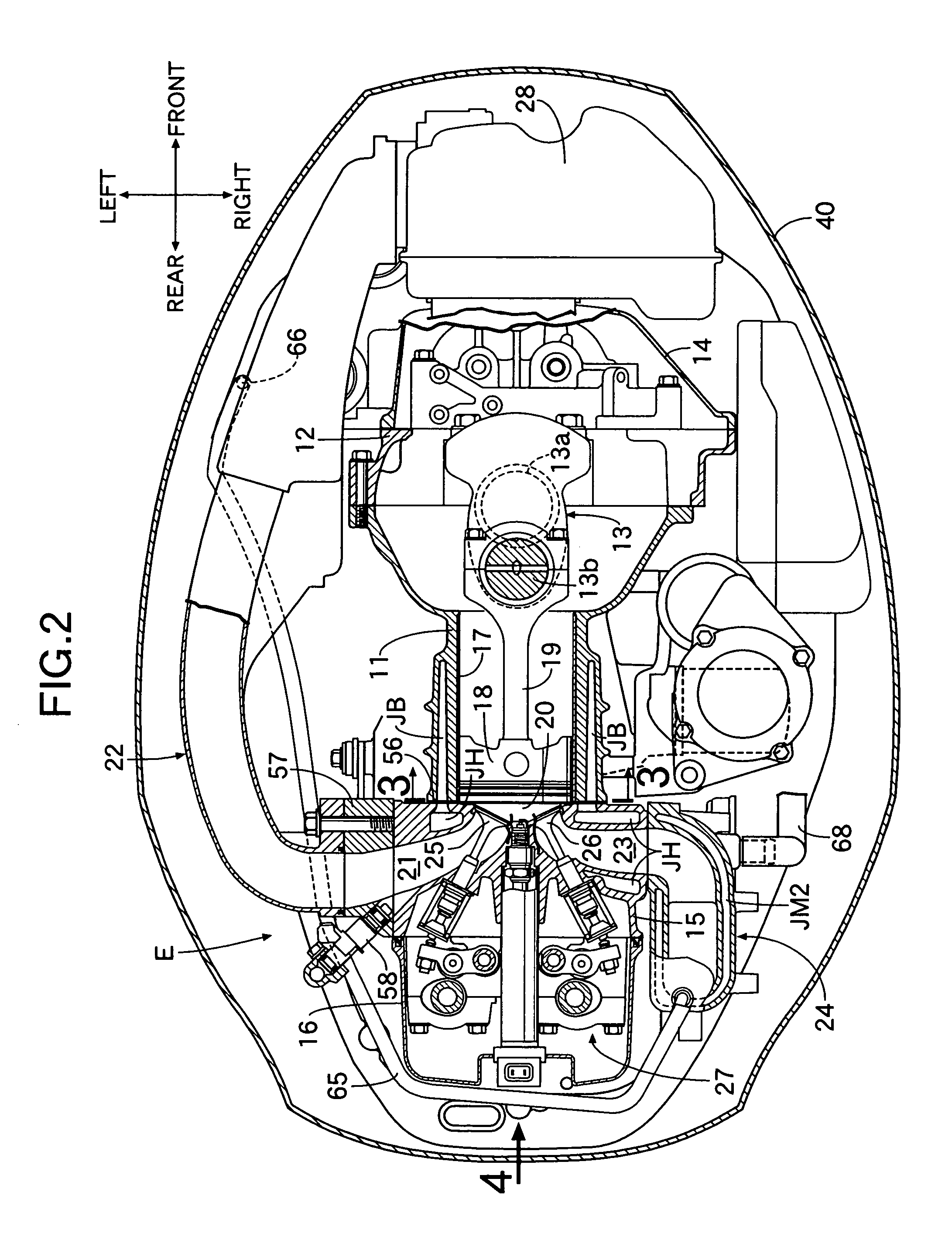
[0012]With the arrangement of the first feature, the cooling water warmed after cooling the higher-temperature portion is supplied to the water jacket formed around the combustion chamber, and hence it is possible to prevent a region around the combustion chamber from being overcooled. Because the cooling water from the higher-temperature portion is supplied to the lower half of the water jacket at this time, it is possible to minimize unevenness in the flow rate of the cooling water flowing through the water jacket on the opposite left and right sides of the cylinder toward the cooling water outlet provided at the upper portion thereof, thereby making uniform the distribution of the temperature around the combustion chamber.
[0013]With the arrangement of the second feature, the water passage is in communication with the water jacket in the position corresponding to the lower half of lowermost one of the plurality of cylinders juxtaposed vertically. Therefore, it is possible to cause the cooling water to flow equally through the water jacket on the opposite left and right sides of the plurality of cylinders, thereby achieving uniform distribution of the temperature around each of the combustion chambers.

Problems solved by technology

Therefore, there is a possibility that the flow rate of the cooling water in various portions of the water jacket becomes uneven, resulting in a degraded cooling effect.

Method used


Image

  • Water-cooled engine
  • Water-cooled engine
  • Water-cooled engine

Examples


Embodiment Construction

[0022]The present invention will now be described by way of an embodiment with reference to the accompanying drawings.

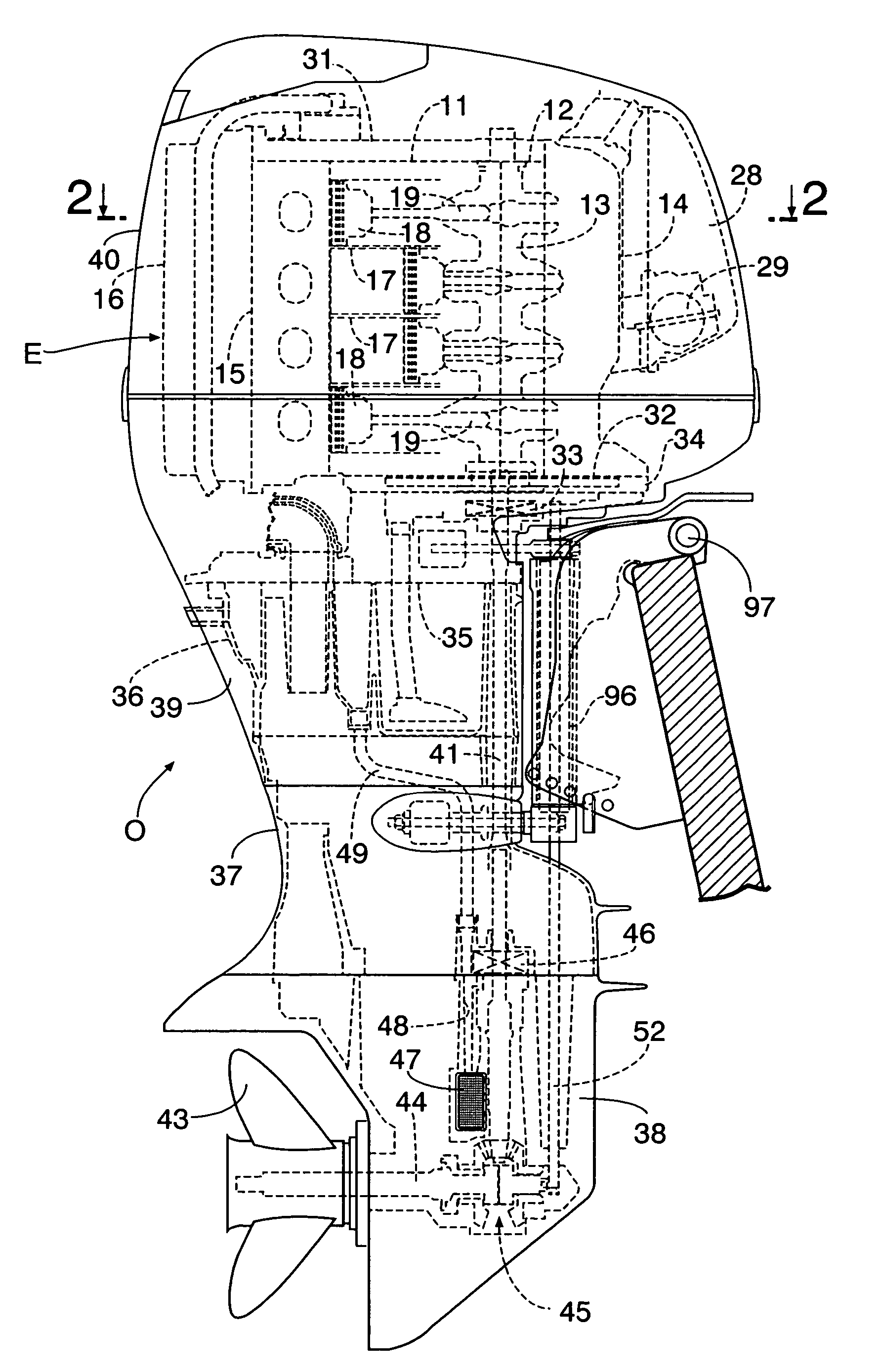
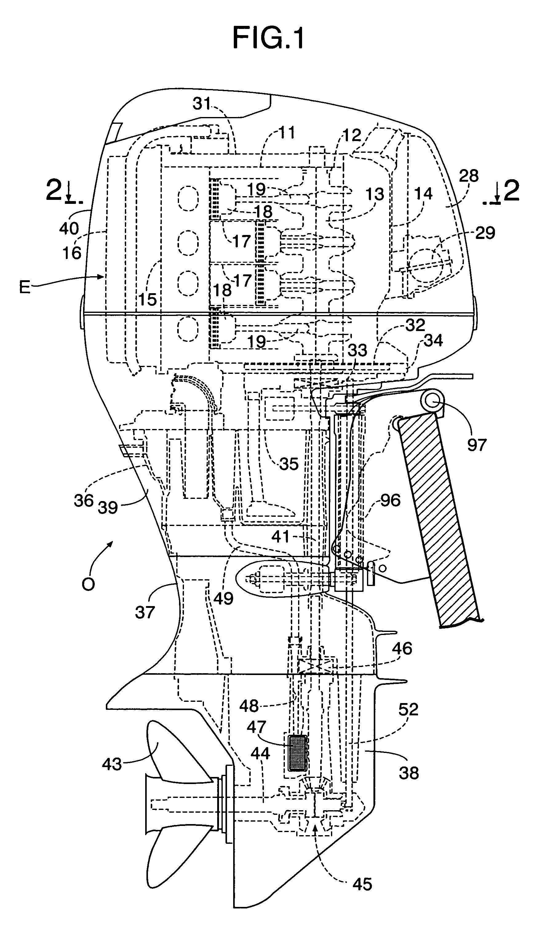
[0023]An outboard engine system O is mounted to a hull to make a steering motion laterally about a steering shaft 96 and to make a tiling motion vertically about a tiling shaft 97. A water-cooled vertical engine E of an in-line 4-cylinder and 4-stroke type mounted on an upper portion of the outboard engine system O, includes: a cylinder block 11; a lower block 12 coupled to a front surface of the cylinder block 11; a crankshaft 13 disposed in a generally vertical direction and supported so that its journals 13a are clamped between the cylinder block 11 and the lower block 12; a crankcase 14 coupled to a front surface of the lower block 12; a cylinder head 15 coupled to a rear surface of the cylinder block 11; and a head cover 16 coupled to a rear surface of the cylinder head 15. Pistons 18 slidably received within four sleeve-shaped cylinders 17 formed by enveloped-c...


PUM


Abstract

In a water-cooled multi-cylinder vertical engine for an outboard engine system, cooling water having passed through an exhaust-manifold cooling water jacket for cooling an exhaust passage within an engine room is supplied to a cylinder-block cooling water jacket provided in a cylinder block through water supply pipes, a branching member and two upper and lower couplings. In this case, the lower coupling is locked below the center of a lowermost cylinder to minimize unevenness in flow rate of the cooling water flowing through a water jacket on opposite left and right sides of a cylinder toward a cooling water outlet provided at an upper portion thereof, thereby making uniform the distribution of the temperature around a combustion chamber, leading to an enhancement in cooling effect.

Description

RELATED APPLICATION DATA[0001]The Japanese priority application No. 2004-97845 upon which the present application is based is hereby incorporated in its entirety herein by reference.BACKGROUND OF THE INVENTION[0002]1. Field of the Invention[0003]The present invention relates to a water-cooled engine comprising: a cylinder having an axis extending generally horizontally; a piston slidably received in the cylinder to define a portion of a combustion chamber; a water jacket formed around the combustion chamber and having a cooling water outlet in its upper portion; and a water passage through which cooling water which has cooled a higher-temperature portion of the engine outside the water jacket is supplied to the water jacket.[0004]2. Description of the Related Art[0005]In general, a water-cooled engine is used as a vertical engine for an outboard engine system. In this type of the water-cooled engine, if a cylinder block and a cylinder head are equally cooled by cooling water, when t...

Claims


Application Information

Patent Timeline
Patent Type & Authority Patents(United States)
IPC IPC(8): F02F1/10F01P3/02F01P3/20F02B61/04F02F1/14
CPCF01P3/202F02B61/045F01P2050/12
Inventor YONEZAWA, MAKOTOTAWA, HIROKIFUKUDA, YOSHIHIKO
Owner HONDA MOTOR CO LTD
Learn More