
Movable shield with switching means for memory card

a memory card and shield technology, applied in the direction of conveying record carriers, coupling device connections, instruments, etc., can solve the problems of electrical interference of various types, and achieve the effect of improving the prior art and eliminating the drawbacks of the known arrangemen

Active Publication Date: 2006-06-27
NOKIA TECH OY
View PDF9 Cites 3 Cited by
  • Summary
  • Abstract
  • Description
  • Claims
  • Application Information

AI Technical Summary

Benefits of technology

[0008]It is the primary aim of the present invention to present an improved connector housing for receiving a memory card, to eliminate the drawbacks of the known arrangements and to improve the prior art.
[0011]In one embodiment of the invention, when the memory card is in its place, the shield part is used as the EMC shield around the memory card, wherein the connecting contacts of the shield part of the cover are used as grounding contacts. When the user wants to remove the memory card, he / she moves the shield part, wherein the shield part switches the advance warning sensors on. In one embodiment, the advance warning sensors comprise at least two contact surfaces, between which a conductive connection is formed by means of the shield part moved in the open position. Thus, an advance warning signal is generated in the device and the device knows that the memory card is being removed and the device has sufficient time to take the necessary steps. In one embodiment, the advance warning signal is only generated when the shield part is entirely in the open position. Thus, for example, the unintentional disconnection of the memory card is avoided, even if the shield part moved slightly.
[0012]In one embodiment of the invention, the shield part of the cover is connected to the ground plane when the cover part is in the use position (i.e., closed) and also when the shield part is between the use position and the open position. Thus, during all the above-mentioned time, the shield part is used as an EMC shield around the memory card, preventing e.g. the damaging of the memory card by the effect of an electric discharge.
[0013]Furthermore, in an advantageous embodiment of the present invention, the direction of operation of the switch function of the advance warning circuit of the connector housing is selected in such a way that the coupling of the advance warning circuit is not connected in the use operation, i.e. when the memory card has been inserted in the connector housing. In other words, the advance warning circuit is thus not coupled as a part of the electric circuit of the device, wherein the signal does not propagate through the cover when the cover is used as the EMC shield. A possible ESC / EMC “attack” to the cover of the connector housing will not be conducted from the shield to the disconnected advance warning circuit and can thus not disturb the operation of the advance warning circuit. First after the cover has been detached from its shield function, the current of the advance warning circuit is conducted in the cover.
[0014]The invention provides significant advantages to the prior art. The advance warning can be implemented in the device in a simple way without space consuming arrangements.
[0015]In an advantageous embodiment, a separate conductor will not be needed for transferring the advance warning signal from one advance warning sensor to another, for example, from a positive pole to a negative pole, since the signal can propagate via the metal shield part.

Problems solved by technology

A problem in the above-presented arrangements is that various types of electrical interference may be coupled to the advance warning circuit.

Method used


Image

  • Movable shield with switching means for memory card
  • Movable shield with switching means for memory card
  • Movable shield with switching means for memory card

Examples


Embodiment Construction

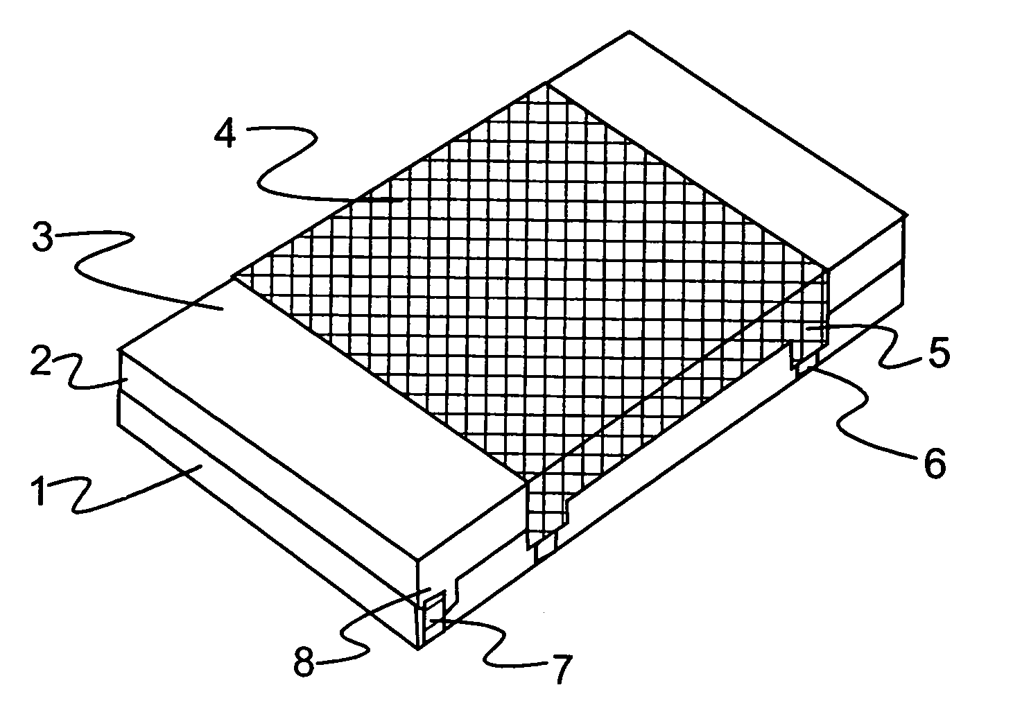
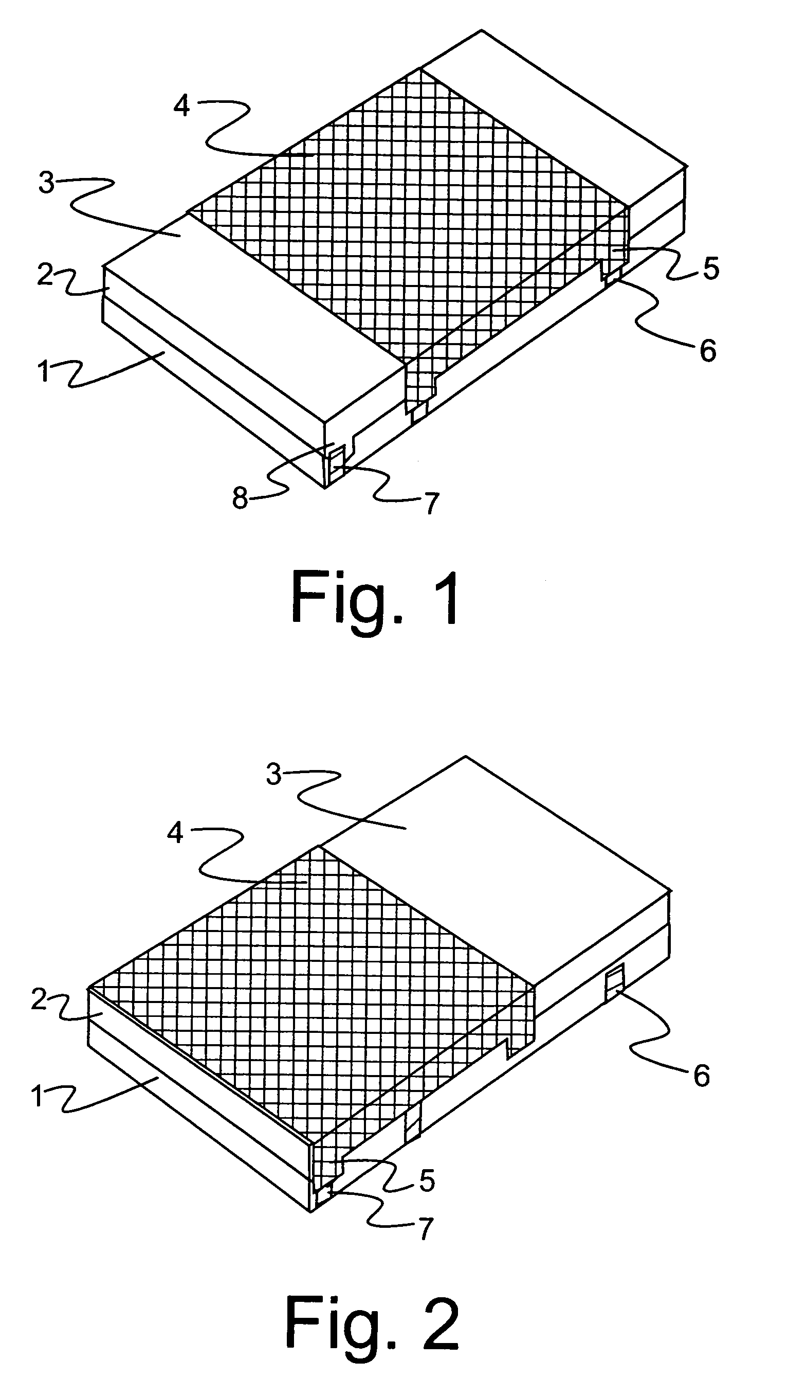
[0023]FIG. 1 shows one embodiment of the connector housing, comprising a bottom part 1 and a cover part 2. The bottom part 1 may also be integrated in the rest of the structure of the device, for example the installation base, wherein the cover part 2 is placed directly on the installation base. The cover part 2, in turn, comprises a frame 3 for the cover as well as a shield part 4 arranged to be movable therein. The shield part 4 comprises switching means 5 which are used as ground switches in the use situation shown in FIG. 1. Thus, the switching means 5 are connected to the grounding contacts 6 of the bottom part 1. The grounding contacts 6 may also be arranged directly on the installation base of the connector housing, i.e., typically on the surface of a circuit board. Said grounding contacts 6 are connected to the ground plane of the device. In some embodiments, the grounding contacts 6 can also be used for other purposes. For example, the signal propagation path can be arrange...


PUM


Abstract

A connector housing for receiving a memory card, the housing comprising at least a bottom part and a cover part which is arranged to be movable in relation to the bottom part and which, in turn, comprises at least a shield part and at least one grounding contact which is arranged to connect the shield part to the ground level of the device, at least when the cover part is closed. The connector housing also comprises at least one signal contact which is arranged to be coupled via the shield part, when the cover part is in the open position. Furthermore, the invention relates to a device comprising a connector housing for a memory card, as well as a method for anticipating the removal of a memory card in the connector housing.

Description

CROSS-REFERENCE TO RELATED APPLICATIONS[0001]This application claims priority under 35 USC §119 to Finnish Patent Application No. 20035228 filed on Dec. 3, 2003.FIELD OF THE INVENTION[0002]The invention relates to a connector housing for receiving a memory card, the housing comprising at least a bottom part and a cover part which is arranged to be movable in relation to the bottom part and which, in turn, comprises at least a shield part and first contact means which are arranged to connect the shield part to the ground plane of the device, at least when the cover part is closed. The invention also relates to a device comprising a connector housing for receiving a memory card, the housing comprising at least a bottom part and a cover part which is arranged to be movable in relation to the bottom part and which, in turn, comprises at least a shield part and first contact means which are arranged to connect the shield part to the ground plane of the device, at least when the cover par...

Claims


Application Information

Patent Timeline
Patent Type & Authority Patents(United States)
IPC IPC(8): H01R13/62G06KG06K7/00G06K17/00G06K19/077H01R12/71H01R13/648H04B1/38
CPCG06K7/0013G06K7/0082G06K13/085G06K13/0862G06K7/0091G06K2017/0064H01R12/71G06K19/077
Inventor LAITINEN, TIMO
Owner NOKIA TECH OY
Learn More