Bumper cross-section with hinges
- Summary
- Abstract
- Description
- Claims
- Application Information
AI Technical Summary
Benefits of technology
Problems solved by technology
Method used
Image
Examples
Embodiment Construction
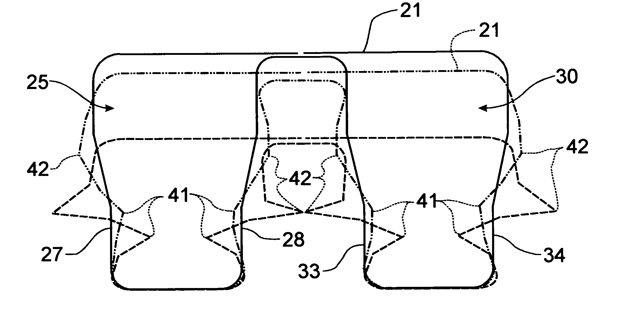
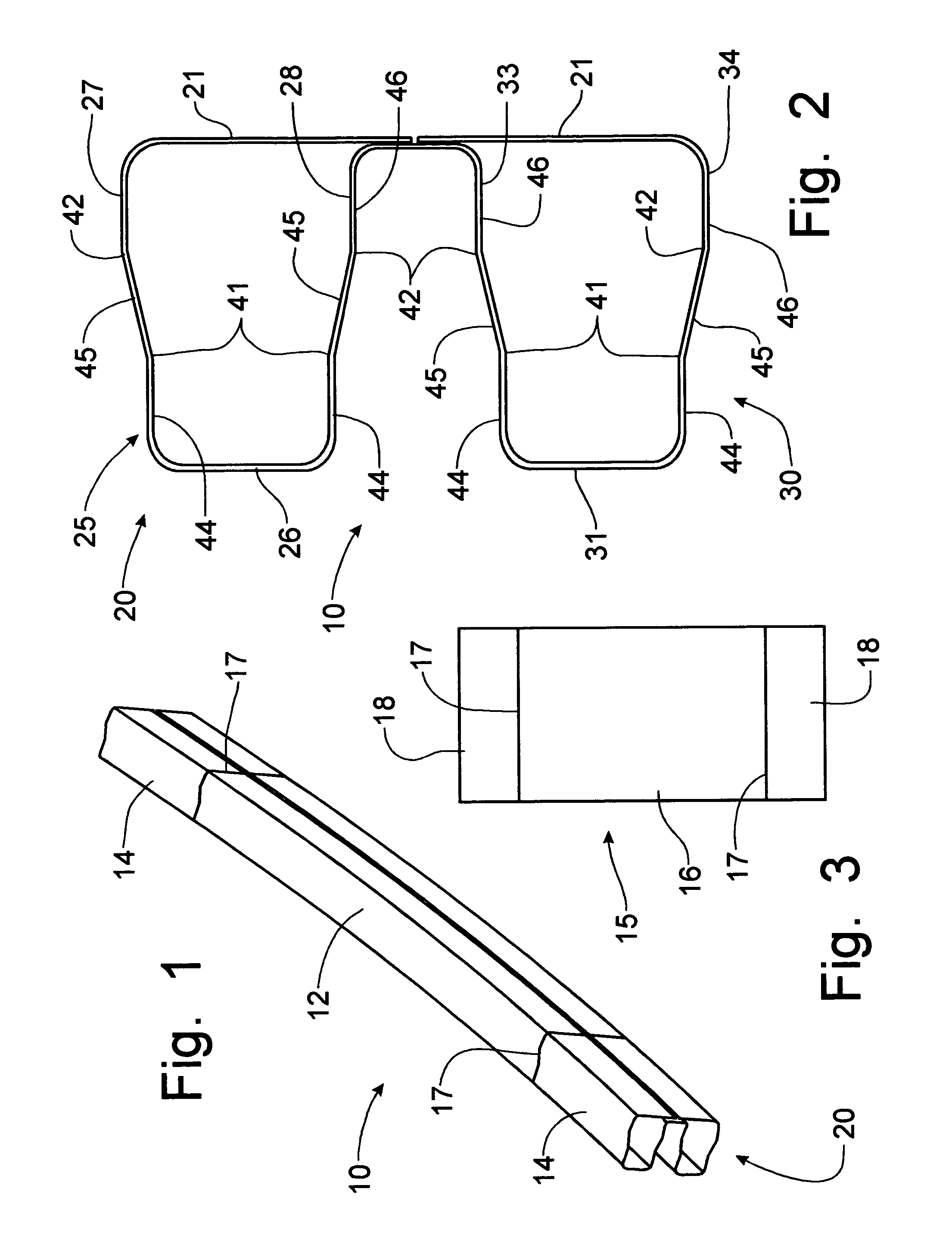
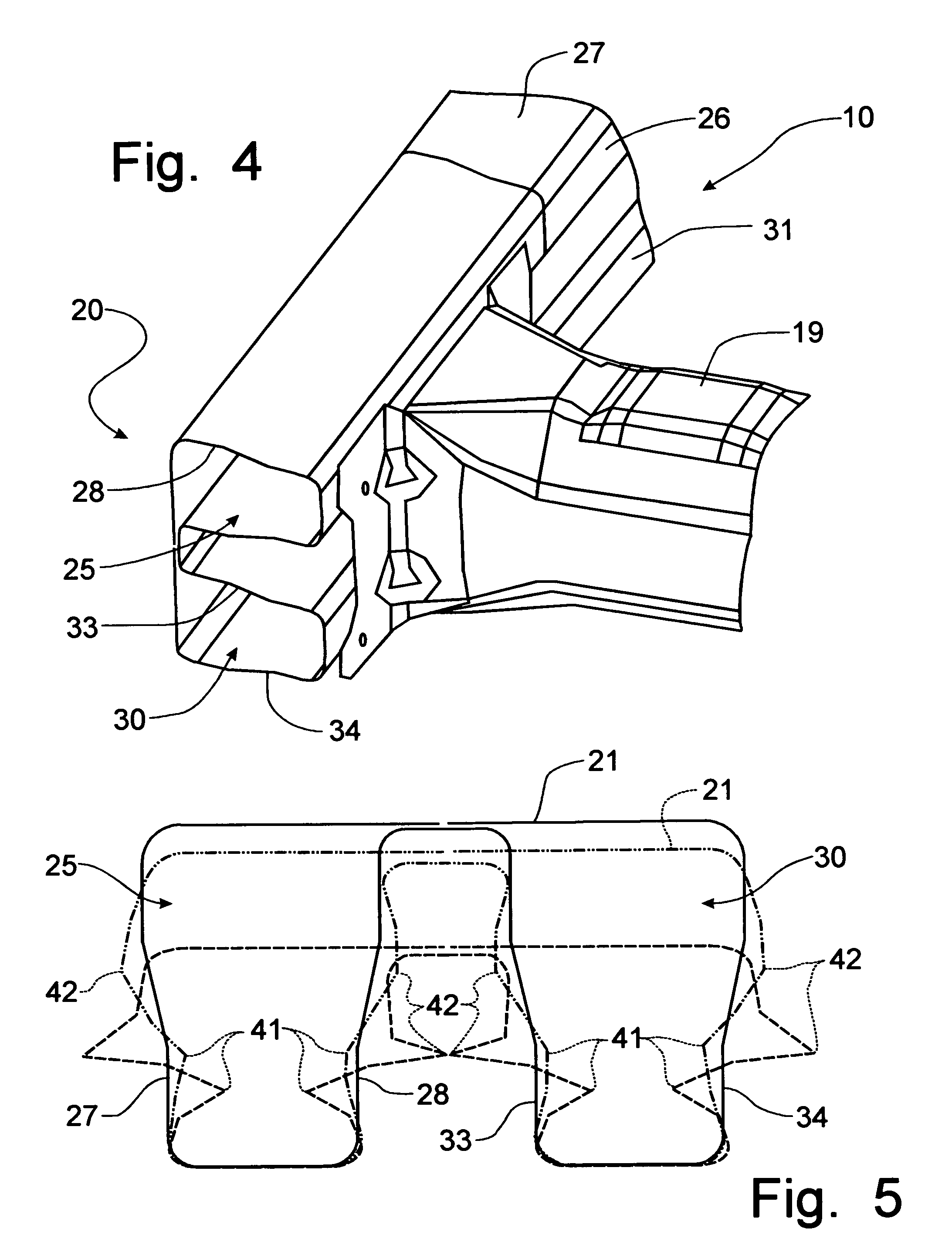
[0030]Referring to FIGS. 1–4, a bumper beam formed according to the principles of the instant invention, to be mounted on the lower frame rails at a forward location of an automobile frame, can best be seen.
[0031]The bumper beam 10 is formed from a tailor welded blank 15, depicted in FIG. 3, with a 0.7 mm gage central piece of sheet metal 16 and with 1.3 mm gage sheet metal pieces 18 laser welded to the opposing lateral edges 17 of the central piece 16 to provide a single sheet metal blank 15 from which the bumper beam 10 is to be formed. The central piece of sheet metal 16 corresponds to the center portion 12 of the bumper beam 10, while the side pieces 18 of the blank 15 correspond to the respective terminal ends 14 of the bumper beam where the lower frame rails 19 are affixed, as is depicted in FIG. 4. Preferably, the central and side pieces 16, 18 of the tailor welded blank 15 are constructed from ultra high strength steel commonly referred to as M220 Martinsite steel.
[0032]The ...
PUM
 Abstract
Description
Claims
Application Information
 - R&D
- Intellectual Property
- Life Sciences
- Materials
- Tech Scout
- Unparalleled Data Quality
- Higher Quality Content
- 60% Fewer Hallucinations
Browse by: Latest US Patents, China's latest patents, Technical Efficacy Thesaurus, Application Domain, Technology Topic, Popular Technical Reports.
© 2025 PatSnap. All rights reserved.Legal|Privacy policy|Modern Slavery Act Transparency Statement|Sitemap|About US| Contact US: help@patsnap.com


