Inertial measurement unit using rotatable MEMS sensors
a technology of inertial measurement and sensor, applied in the direction of speed/acceleration/shock measurement, instruments, surveying and navigation, etc., can solve the problems of inability to directly determine, inertial calculation based on the measurement of the sensor's output operating under dynamic conditions, and can contain alternately positive and negative errors, so as to improve the sense of accuracy
- Summary
- Abstract
- Description
- Claims
- Application Information
AI Technical Summary
Benefits of technology
Problems solved by technology
Method used
Image
Examples
first embodiment
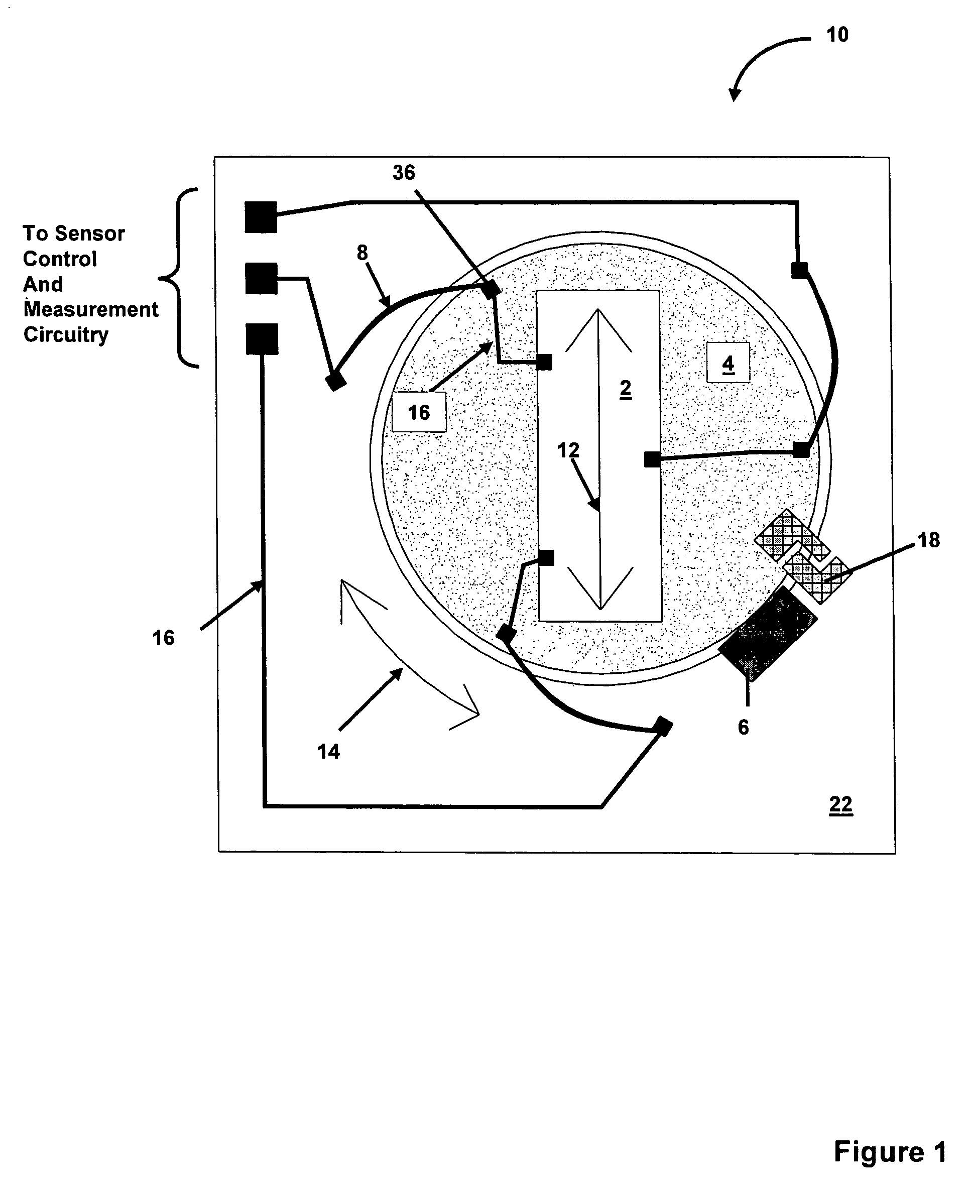
[0028]FIG. 1 is a schematic plan view of a MEM inertial sensor 10 according to the present invention. The micromechanical inertial sensor 10, comprises a base 22 providing mechanical support for a rotatable micromechanical stage 4. A MEM inertial sensing element 2, having an inertial sense axis 12 is disposed on stage 4. An actuator 6 is operatively coupled to micromechanical stage 4, and rotates stage 4 about a rotational axis that is substantially perpendicular to sense axis 12 of sense element 2 (i.e. about an axis extending out of the plane of FIG. 1) and in the rotational direction as indicated by the arc 14.
[0029]Actuator 6 for rotating the stage 4 may further include mechanical stops 18, or indexing gears, latches or the like for orienting and positioning stage 4, at known rotational positions. Actuator 6 for rotating micromechanical stage 4 can comprise an electrostatic actuator, an electromagnetic actuator, a shape memory alloy actuator, a phase change based actuator, a pie...
second embodiment
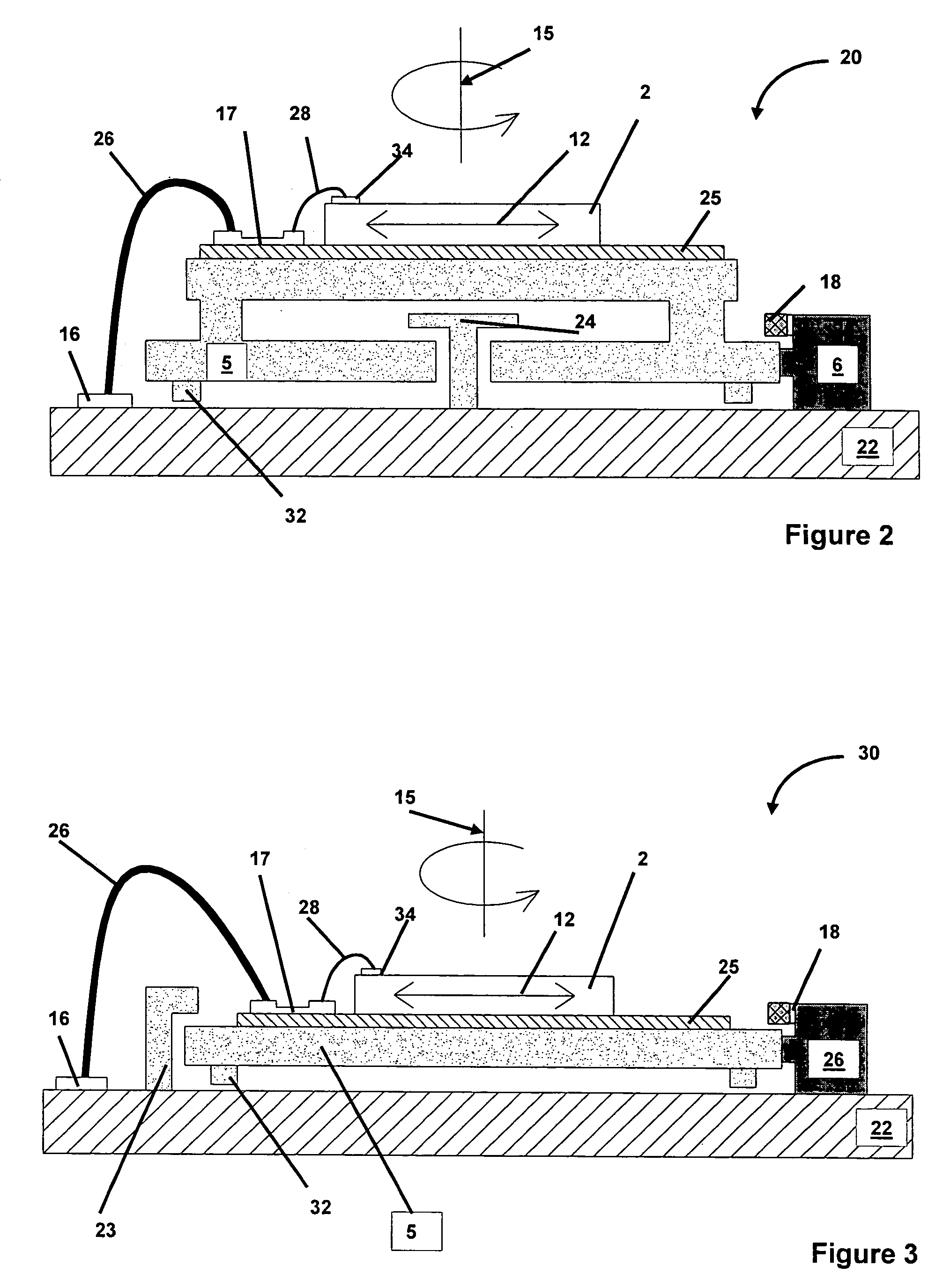
[0033]FIG. 2 shows a schematic cross section view of a MEM inertial sensor 20 with integral rotational means according to the present invention. The MEM inertial sensor 20 comprises a base 22 providing mechanical support for a rotatable micromechanical stage 5. Stage 5 can be fabricated using LIGA technologies. A MEM inertial sensing element 2, having an inertial sense axis 12 is disposed on stage 5. Stage 5 is rotatably affixed to base 22 by a hub 24. An actuator 6 is operatively coupled to micromechanical stage 5, and rotates stage 5 about a rotational axis 15 which is substantially perpendicular to the sense axis 12 of the sense element 2. Actuator 6 for rotating micromechanical stage 5 can comprise an electrostatic actuator, an electromagnetic actuator, a shape memory alloy actuator, a phase change based actuator, a piezoelectric actuator or a thermal actuator. The actuator 6 can be mechanically coupled to rotate stage 5 through gears, ratchets, indexing pawls, etc. Actuator 6 f...
third embodiment
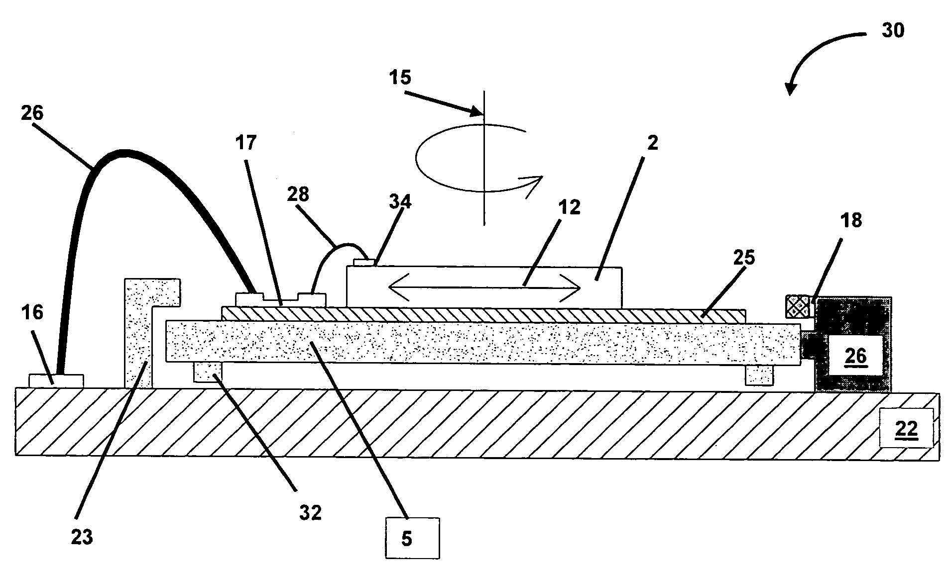
[0037]FIG. 3 shows a schematic cross section view of a MEM inertial sensor 30 with integral rotational means according to the present invention. The MEM inertial sensor 30 comprises a base 22 providing mechanical support for a rotatable micromechanical stage 5. Stage 5 can be fabricated using LIGA technologies. A MEM inertial sensing element 2, having an inertial sense axis 12 is disposed on stage 5. Stage 5 is rotatably constrained to base 22 by restraining clips 23, that slideably engage stage 5. Restraining clips 23 are attached to base 22 and are spaced about the perimeter of stage 5 (e.g. typically at three locations). An actuator 6 is operatively coupled to micromechanical stage 5, and rotates stage 5 about a rotational axis 15 which is substantially perpendicular to the sense axis 12 of the sense element 2. Actuator 6 for rotating micromechanical stage 5 can comprise an electrostatic actuator, an electromagnetic actuator, a shape memory alloy actuator, a phase change based ac...
PUM
 Abstract
Description
Claims
Application Information
 - R&D
- Intellectual Property
- Life Sciences
- Materials
- Tech Scout
- Unparalleled Data Quality
- Higher Quality Content
- 60% Fewer Hallucinations
Browse by: Latest US Patents, China's latest patents, Technical Efficacy Thesaurus, Application Domain, Technology Topic, Popular Technical Reports.
© 2025 PatSnap. All rights reserved.Legal|Privacy policy|Modern Slavery Act Transparency Statement|Sitemap|About US| Contact US: help@patsnap.com


