
Method for iterative determination of distance between receiving station and transmitting station and also calculating unit and computer software product

Inactive Publication Date: 2006-06-20
NOKIA SIEMENS NETWORKS GMBH & CO KG
View PDF4 Cites 43 Cited by
  • Summary
  • Abstract
  • Description
  • Claims
  • Application Information

AI Technical Summary

Benefits of technology

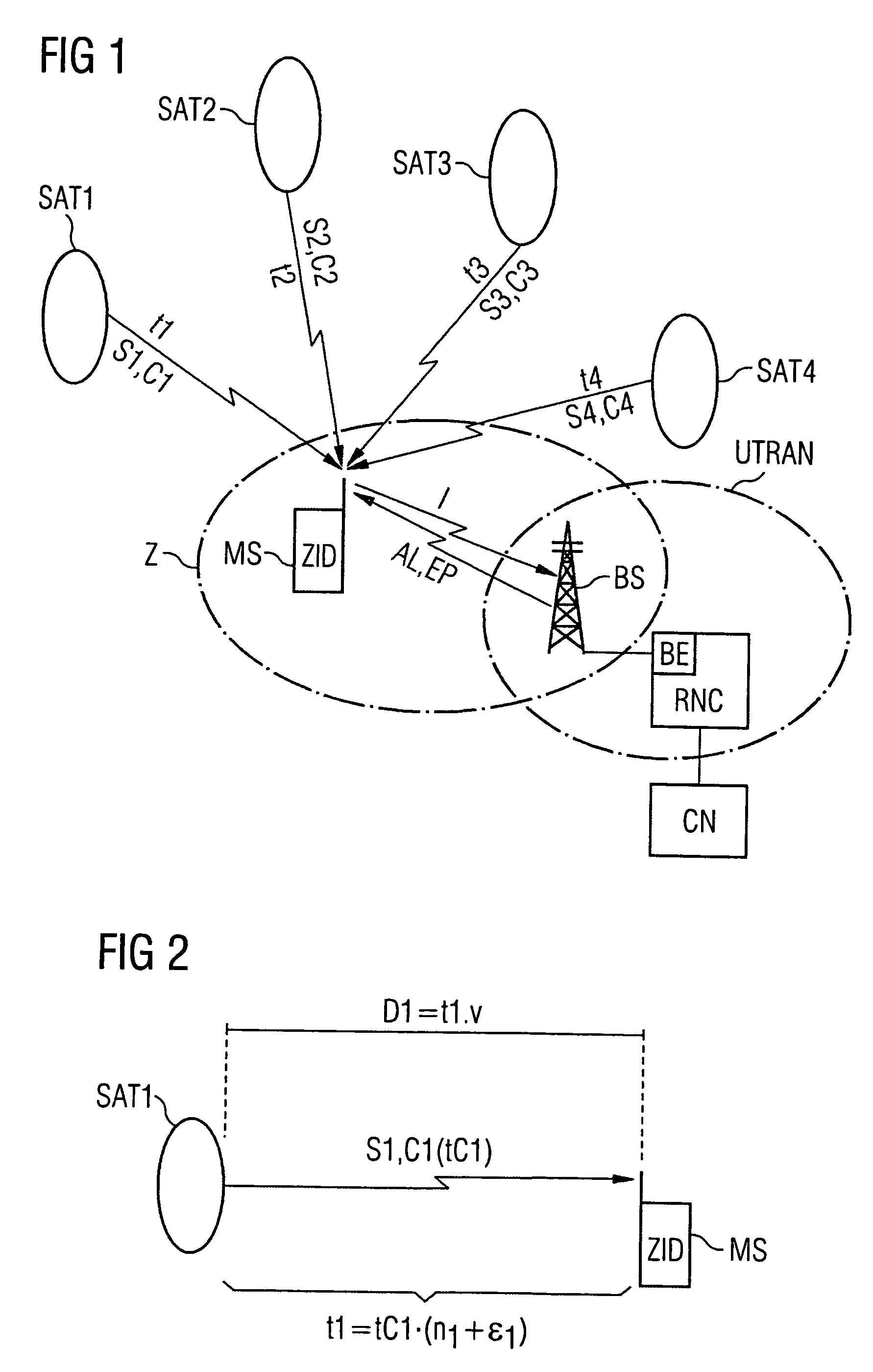
[0009]In the method according to the invention for the iterative determination of the distance between a receiving station and a transmitting station, information is received by a calculating unit concerning a signal from the transmitting station that is received by the receiving station, the signal being provided with a code. A number of integral multiples of the code come into the receiving station during the signal transfer time that the signal requires to travel between the transmitting station and the receiving station. During the first iteration the number of integral multiples in the code is calculated and the calculated number is used in the second iteration at least, without a fresh calculation being carried out. As a result of the fact that in the second iteration at least, a fresh calculation of the number of integral multiples is not made, the computing power required can be reduced.
[0011]It is advantageous that a rough estimation of the position of the receiving station is used to calculate the number of integral multiples of the code. The rough estimation of the position of the receiving station, together with an estimation of the position of the transmitting station, allows a sufficiently precise estimation of the distance between the receiving station and the transmitting station to be made. From the distance calculated in the above way it is possible to calculate the exact number of integral multiples if the position of the transmitting station is known almost exactly (in satellites, for example, from their known stable orbits) and if the position of the receiving station is known with an accuracy greater than the half-wavelength of the code. Here, the wavelength of the code is obtained by multiplying the duration of the code by the propagation velocity of the signal, that is, in vacuum, by the speed of light. The exact number of integral multiples is consequently determined in the very first iteration of the method and is no longer necessary in all subsequent iterations. When multiplied by the wavelength of the code, the number of integral multiples corresponds to a minimum distance between the transmitting station and receiving station. The above minimum distance is one of the addends used to calculate the actual distance in the first and at least, in the second iteration.
[0013]The number of iterations required to determine the distance between the receiving station and the transmitting station can be reduced, that is, the computing power required can be reduced, if a value other than zero is used in the very first iteration for the signal's signal transfer time.

Problems solved by technology

Since the phase offset is, however, measured using only one code cycle, the total transfer time that the signal requires to cover the distance between the satellite and the station cannot be determined from the phase offset alone.

Method used


Image

  • Method for iterative determination of distance between receiving station and transmitting station and also calculating unit and computer software product
  • Method for iterative determination of distance between receiving station and transmitting station and also calculating unit and computer software product

Examples


Embodiment Construction

[0017]Reference will now be made in detail to the preferred embodiments of the present invention, examples of which are illustrated in the accompanying drawings, wherein like reference characters refer to like elements throughout.

[0018]A receiving station is any station that is able to receive signals. In the text that follows, a mobile station is considered to be a receiving station. A mobile station is, for example, a mobile phone or also a device the location whereof can be moved, for the transmission of image and / or sound data, for sending faxes, for sending short messages via a Short Message Service (SMS), for sending emails and for Internet access. It is therefore a general transmitting and / or receiving unit in a radio communications system.

[0019]A transmitting station is understood to be a station that is able to transmit a signal provided with a code, i.e. a modulated signal. A transmitting station may be assigned to a radio communications system or be an external station th...


PUM


Abstract

Information received by a calculating unit via a signal from a transmitting station to a receiving station is provided with a code, a number of integral multiples of the code coming into the receiving station during the signal transfer time that the signal requires to travel between the transmitting station and the receiving station. During a first iteration, the number of integral multiples of the code is calculated and the calculated number is used at least in a second iteration without a fresh calculation being carried out.

Description

CROSS REFERENCE TO RELATED APPLICATIONS[0001]This application is based on and hereby claims priority to German Application No. 103 16 290.9 filed on 9 Apr. 2003, the contents of which are hereby incorporated by reference.BACKGROUND OF THE INVENTION[0002]1. Field of the Invention[0003]The invention discloses a method for the iterative determination of the distance between a receiving station and a transmitting station and also a corresponding calculating unit, a corresponding computer software product and a corresponding data carrier.[0004]2. Description of the Related Art[0005]The GPS method (GPS: Global Positioning System) for determining the position of a station is based on the principle of measuring signal transfer times between satellites having known positions and a GPS receiver that is installed in a station. The transfer time for a signal is proportional to the distance of the respective satellite from the station, that is, the distance between a satellite and the station ca...

Claims


Application Information

Patent Timeline
IPC IPC(8): G01S3/02G01S1/00G01S5/00G01S19/42
CPCG01S5/0036G01S19/42G01S19/252G01S19/258G01S19/256
Inventor STRICKLAND, STUARTWARKEN, MARKUS
Owner NOKIA SIEMENS NETWORKS GMBH & CO KG
Learn More