
System and method for inferring an electronic rendering of an environment

a technology of electronic rendering and environment, applied in the field of system and method for inferring an electronic rendering of an environment, can solve the problems of reducing visibility, and affecting the operation of the system

Inactive Publication Date: 2006-06-20
ARRIS ENTERPRISES LLC
View PDF27 Cites 73 Cited by
  • Summary
  • Abstract
  • Description
  • Claims
  • Application Information

AI Technical Summary

Benefits of technology

[0033]While the invention has been described in conjunction with specific embodiments thereof, additional advantages and modifications will readily occur to those skilled in the art. The invention, in its broader aspects, is therefore not limited to the specific details, representative apparatus, and illustrative examples shown and described. Various alterations, modifications and variations will be apparent to those skilled in the art in light of the foregoing description. Thus, it should be understood that the invention is not limited by the foregoing description, but embraces all such alterations, modifications and variations in accordance with the spirit and scope of the appended claims.

Problems solved by technology

However, there are a number of real-world cases where this information is unavailable.
Databases containing building floor plans are being built up in some urban areas, but floor plans can change frequently, and many incidents occur in older and abandoned structures for which this data is unavailable.
Military operations on foreign soil will often require operation in environments for which such data are unknown or intentionally withheld by an adversary.
This issue particularly affects emergency operations, such as firefighting, since lack of power, dense smoke, and other conditions can reduce visibility to inches.
The a priori collection of topological information, such as floor plans, is often impractical; the a priori collection of situational information, such as blocked or impassable routes, structural damage, environmental temperatures, adversary presence, presence of hazardous materials or deployment of chemical or biological weapons, is by definition impossible.

Method used


Image

  • System and method for inferring an electronic rendering of an environment
  • System and method for inferring an electronic rendering of an environment
  • System and method for inferring an electronic rendering of an environment

Examples


Embodiment Construction

[0013]While this invention is susceptible of embodiments in many different forms, there are shown in the figures and will herein be described in detail specific embodiments, with the understanding that the present disclosure is to be considered as an example of the principles of the invention and not intended to limit the invention to the specific embodiments shown and described. Further, the terms and words used herein are not to be considered limiting, but rather merely descriptive. In the description below, like reference numbers are used to describe the same, similar, or corresponding parts in the several views of the figures.

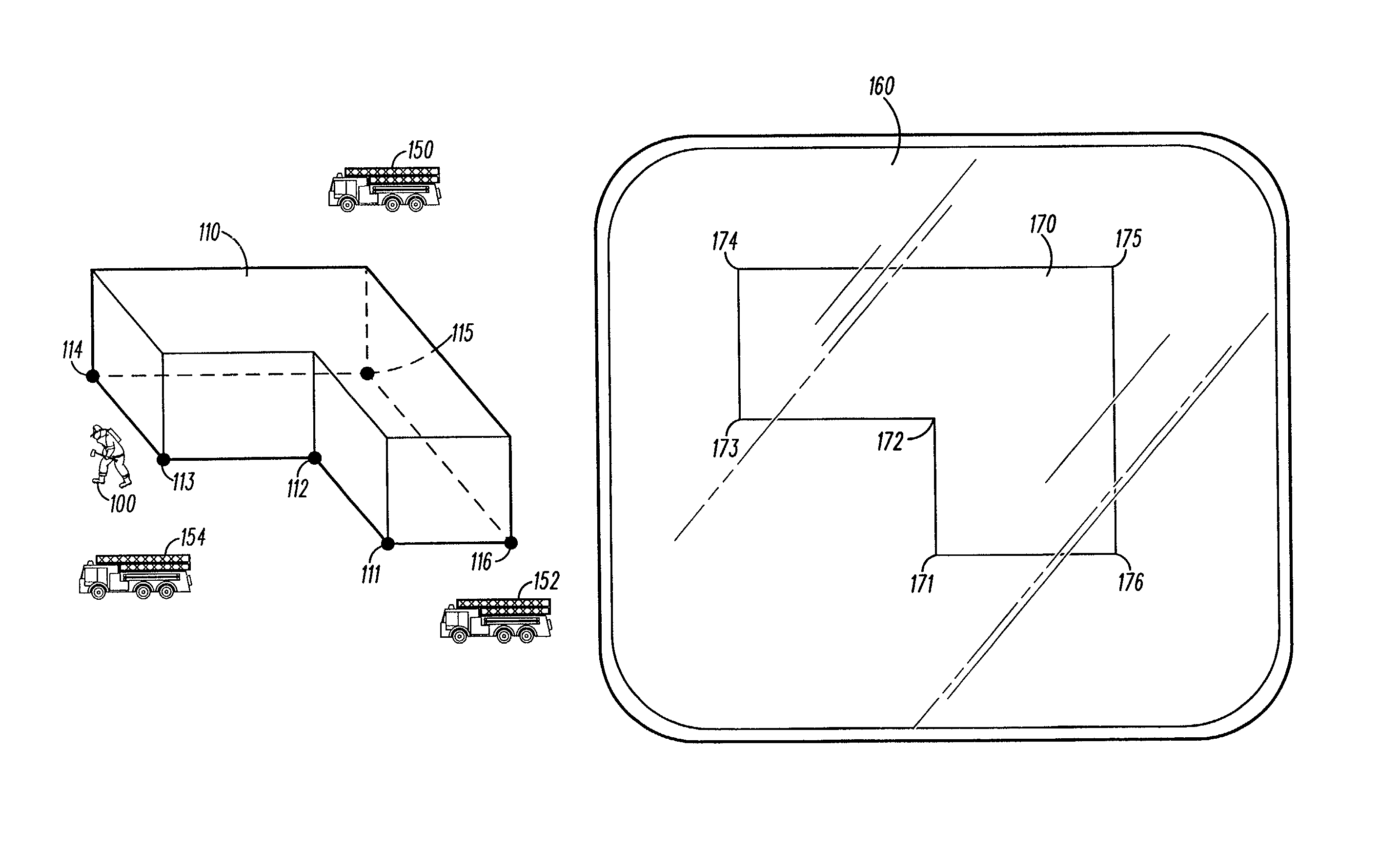
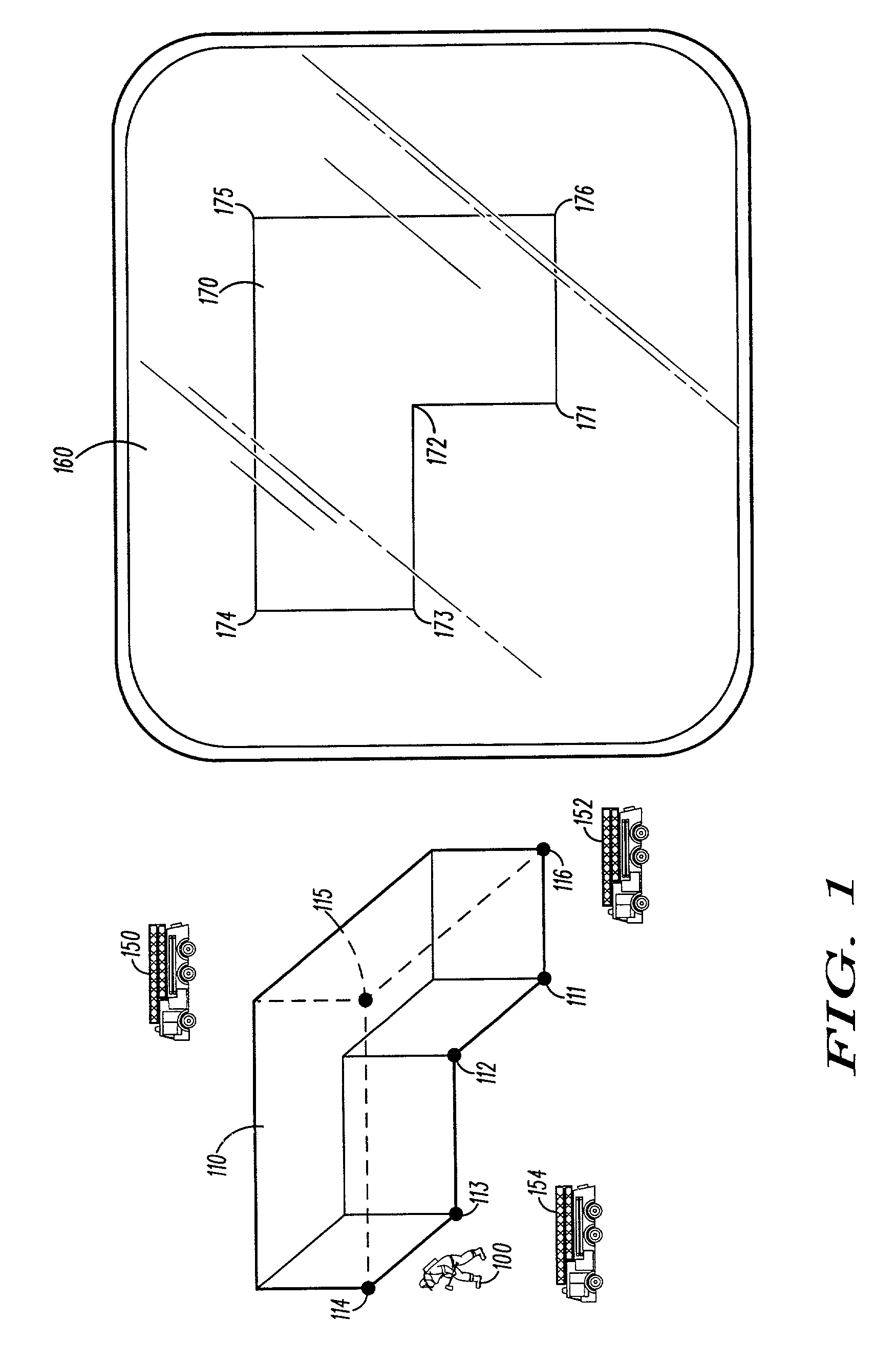
[0014]While the invention has applications in a number of areas, scenarios for fireground operations, and particularly fireground operations within buildings, are currently the best developed. As such, these scenarios are predominantly used herein by way of example. This is done for the sake of clarity and consistency, and is not intended to imply any corre...


PUM


Abstract

A system and method for inferring an electronic rendering (170) of an environment (110) comprises a plurality of devices (341 and 345), and a processing device. Each wireless device is capable of determining a distance between a neighboring wireless device. Moreover, each device is capable of performing at least one of the following: determining an environmental attribute of the environment, and determining a location of an object in the environment. The processing device gathers information determined from the plurality of devices and infers the electronic rendering of the environment based on the information gathered.

Description

REFERENCE TO RELATED APPLICATION[0001]The present application is related to U.S. application Ser. No. 10 / 145,257, filed May 14, 2002, titled “System and Method for Inferring a Set of Characteristics of an Environment with Location-Capable devices” by Johnson et al. commonly owned together with this application by Motorola, Inc.FIELD OF THE INVENTION[0002]The present invention relates generally to a system and method for inferring an electronic rendering of an environment.BACKGROUND OF THE INVENTION[0003]Location systems, well known in the art, have reached a level of sophistication where accurate location coverage in buildings and other confined areas is becoming practical. Spread-spectrum and ultra-wide-band (“UWB”) technologies have offered dramatic improvements in timing accuracy, distributed systems have emerged to address coverage issues, and feasible implementations of portable inertial navigation systems (“PINS”) are emerging that can address short-term stability and coverage...

Claims


Application Information

Patent Timeline
IPC IPC(8): G08B1/08G08B3/10G08B21/12G08B25/10H04L12/56
CPCG08B25/10G08B21/12G08B3/1083G01S2205/002
Inventor PERKINS, MATTHEW R.O'DEA, ROBERT J.JOHNSON, MARK J.PATWARI, NEAL K.
Owner ARRIS ENTERPRISES LLC
Learn More