
Portable air horn apparatus

a portable, horn technology, applied in the direction of noise, sound producing devices, mechanical vibration separation, etc., can solve the problems of unsuitable professional use, further reducing the number of devices used before the replacement of the canister, etc., and achieve the effect of convenient use and light weigh

Active Publication Date: 2006-06-20
WOODSCAN INDS
View PDF38 Cites 6 Cited by
  • Summary
  • Abstract
  • Description
  • Claims
  • Application Information

AI Technical Summary

Benefits of technology

"The invention is a portable air horn apparatus that can be used intermittently. It includes an air horn, an air compressor, an air conduit, an electric motor, a portable source of electrical energy, and electrical circuitry. The apparatus can be used with or without a portable power source. It requires no reservoir for compressed air and operates at a constant pressure, resulting in consistent sound volume. The device is portable, lightweight, and convenient to use."

Problems solved by technology

However, gas canisters contain a finite amount of compressed gas that allows only a few uses before the canister has to be changed.
Even worse, the valve devices tend to allow leakage of the gas from the canisters, thus further reducing the number of uses of the device before replacement of the canister is necessary.
Gas leakage can also lead costly or dangerous situations in which an apparatus is unexpectedly found to be inoperative due to leakage and necessary warnings cannot be given, at least until a new canister can be obtained.
The unreliability of apparatus of this kind makes it unsuitable for professional use.

Method used


Image

  • Portable air horn apparatus
  • Portable air horn apparatus
  • Portable air horn apparatus

Examples


Embodiment Construction

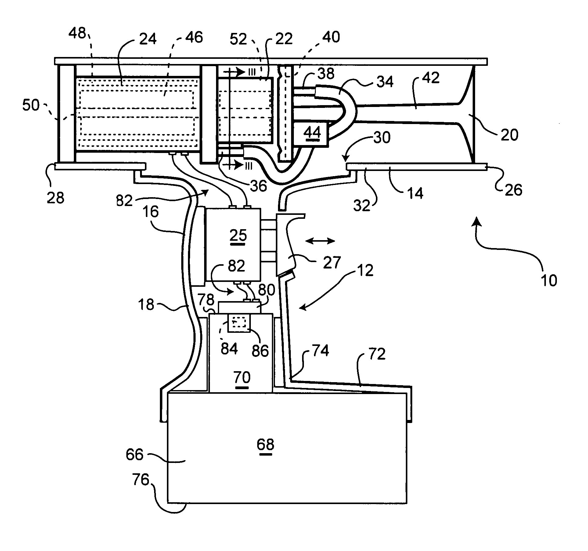
[0016]The device shown in FIG. 1 of the accompanying drawings is one embodiment of a portable air horn apparatus 10 according to the present invention. The apparatus 10 has a housing 12 consisting of two main parts. A first part is in the form of an elongated tubular element 14, and a second part is in the form of an elongated member 16 attached to the tubular element 14 at one end of the elongated member and extending from the tubular element 14 at an angle, preferably in the range of about 75 to 105 degrees, and optionally around 90 degrees. The apparatus consequently resembles a pistol with the tubular element 14 forming the “barrel” and the elongated member 16 forming a handle 18 in the form of a “pistol grip” that can be grasped by a user in one hand to carry and operate the apparatus. The housing 12 serves the purpose of physically supporting and interconnecting the parts of the apparatus so that they form a unitary whole. The housing 12 also encloses and protects most of the ...


PUM


Abstract

A portable air horn apparatus. The apparatus includes an air horn adapted to generate sound when supplied with air under pressure, an air compressor adapted to generate air under pressure, an air conduit interconnecting the compressor and the air horn enabling the air under pressure generated by the compressor to be supplied to the air horn, an electric motor adapted to operate the air compressor when energized, a portable source of electrical energy, and electrical circuitry electrically connecting the portable source of electrical energy to the electric motor to enable the electric motor to be energized. The circuitry includes a manually operable on-off switch having a first position opening the circuitry and a second position closing the circuitry. A housing is provided for physically supporting and interconnecting at least the air horn, compressor, electric motor, on-off switch and portable source of electrical energy, and includes a handle adapted to be manually graspable by a user of the device.

Description

BACKGROUND OF THE INVENTION[0001]I. Field of the Invention[0002]This invention relates to air horns used to provide warning sounds over wide distances. More particular, the invention relates to air horn apparatus that is portable.[0003]II. Background Art[0004]Air horns are commonly used as warning devices because they are capapble of providing very loud and distinctive sounds that carry over large distances. For example, air horns are used in the mining and construction industry to provide warnings when blasting is about to take place.[0005]A very common kind of portable air horn apparatus consists of an air horn attached to a valve device that can be fitted to the neck of a compressed gas canister. The valve device includes a trigger that, when operated, allows compressed gas from the canister to operate the air horn. Devices of this kind are relatively inexpensive and lightweight and can generate sound at a high volume. However, gas canisters contain a finite amount of compressed ...

Claims


Application Information

Patent Timeline
Patent Type & Authority Patents(United States)
IPC IPC(8): G10K7/02G10K9/22G08B3/00G08B3/06
CPCG08B3/06
Inventor WOODS, DAVID TERRY
Owner WOODSCAN INDS
Learn More