
Solid bowl screw centrifuge comprising a distributor

a distributor and centrifuge technology, applied in the direction of centrifuges, rotary centrifuges, etc., can solve the problems of not achieving a reduction of relative velocity, insufficient measurement for effective reduction of swirls, and high expenditures, so as to reduce the relative velocity of the material to be centrifuged

Inactive Publication Date: 2006-06-13
WESTFALIA SEPARATOR AG
View PDF42 Cites 9 Cited by
  • Summary
  • Abstract
  • Description
  • Claims
  • Application Information

AI Technical Summary

Benefits of technology

[0004]From U.S. Patent Document U.S. Pat. No. 5,403,486, it is known to provide the area of the feeding of material to be centrifuged, in the widest sense of the word, the distributor, of a solid bowl screw centrifuge with a larger number of outlet openings which are aligned at various angles with respect to one another. However, this requires relatively high expenditures and, in addition, no lowering of the relative velocity is achieved.
[0006]The invention develops the solid bowl screw centrifuge of the above-mentioned type such that the relative velocity of the material to be centrifuged is reduced in a constructively simple manner when entering the liquid surface.
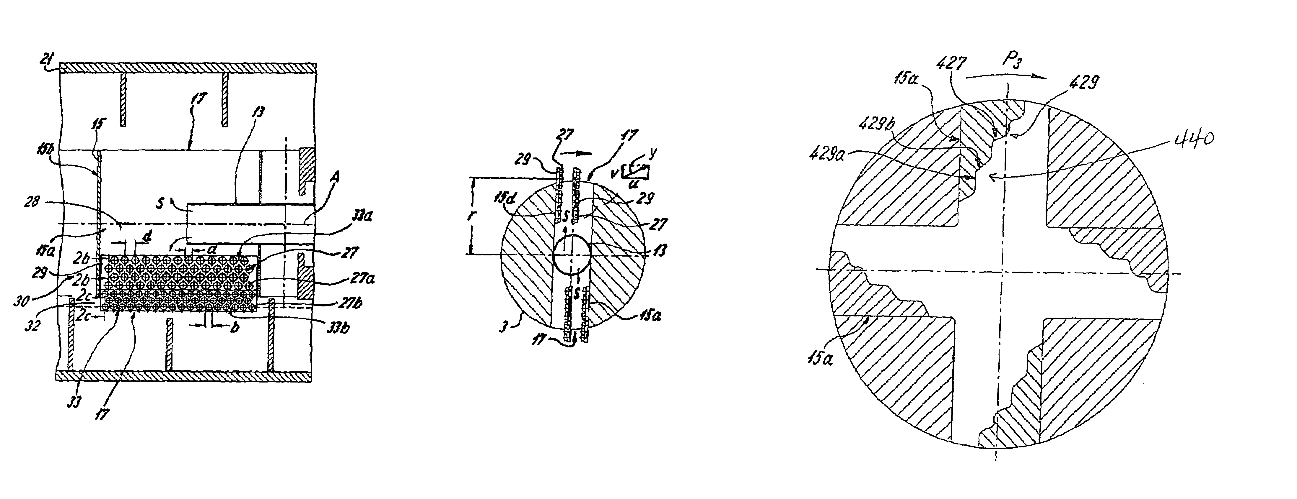
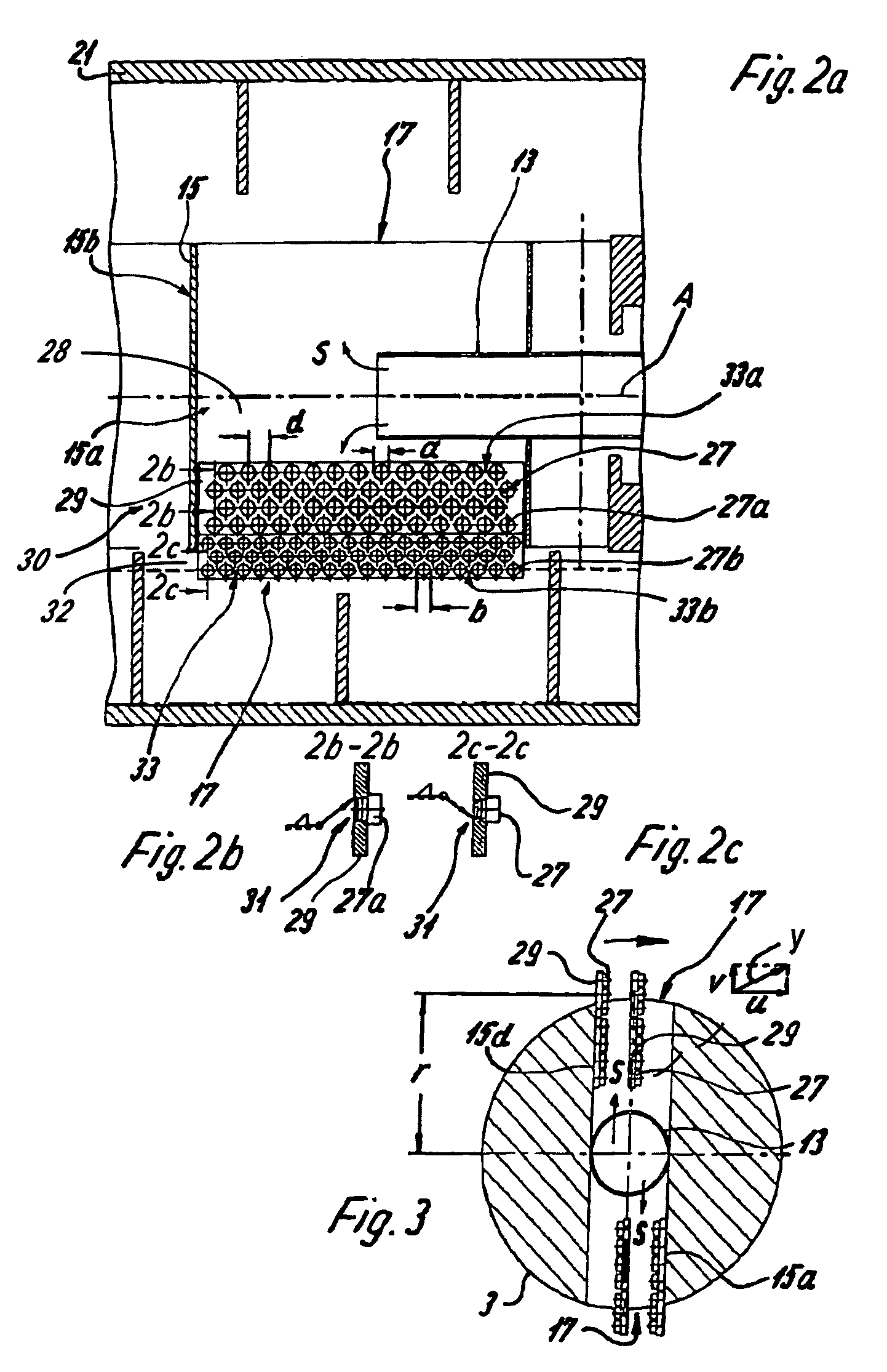
[0009]The embodiments of the present invention provide for an effective and nevertheless simple and relatively inexpensive manner such that at least the essential portion of the material to be centrifuged, but preferably the entire material to be centrifuged, can no longer flow in a direct radial path out of the inflow tube into the centrifugal chamber. Here, the word “radial” applies to the direction on the distributor wall in which the material to be centrifuged will essentially flow into the centrifuging chamber during the rotation of the distributor as a result of the centrifugal force. The term “radial” may also comprise an axial movement component and / or a circumferential component. It is important that at least the essential portion of the material to be centrifuged does not flow directly “in the direction of the centrifugal force” into the centrifuging chamber.

Problems solved by technology

However, this requires relatively high expenditures and, in addition, no lowering of the relative velocity is achieved.
However, this measure is not sufficient for an effective reduction of swirls.

Method used


Image

  • Solid bowl screw centrifuge comprising a distributor
  • Solid bowl screw centrifuge comprising a distributor
  • Solid bowl screw centrifuge comprising a distributor

Examples


Embodiment Construction

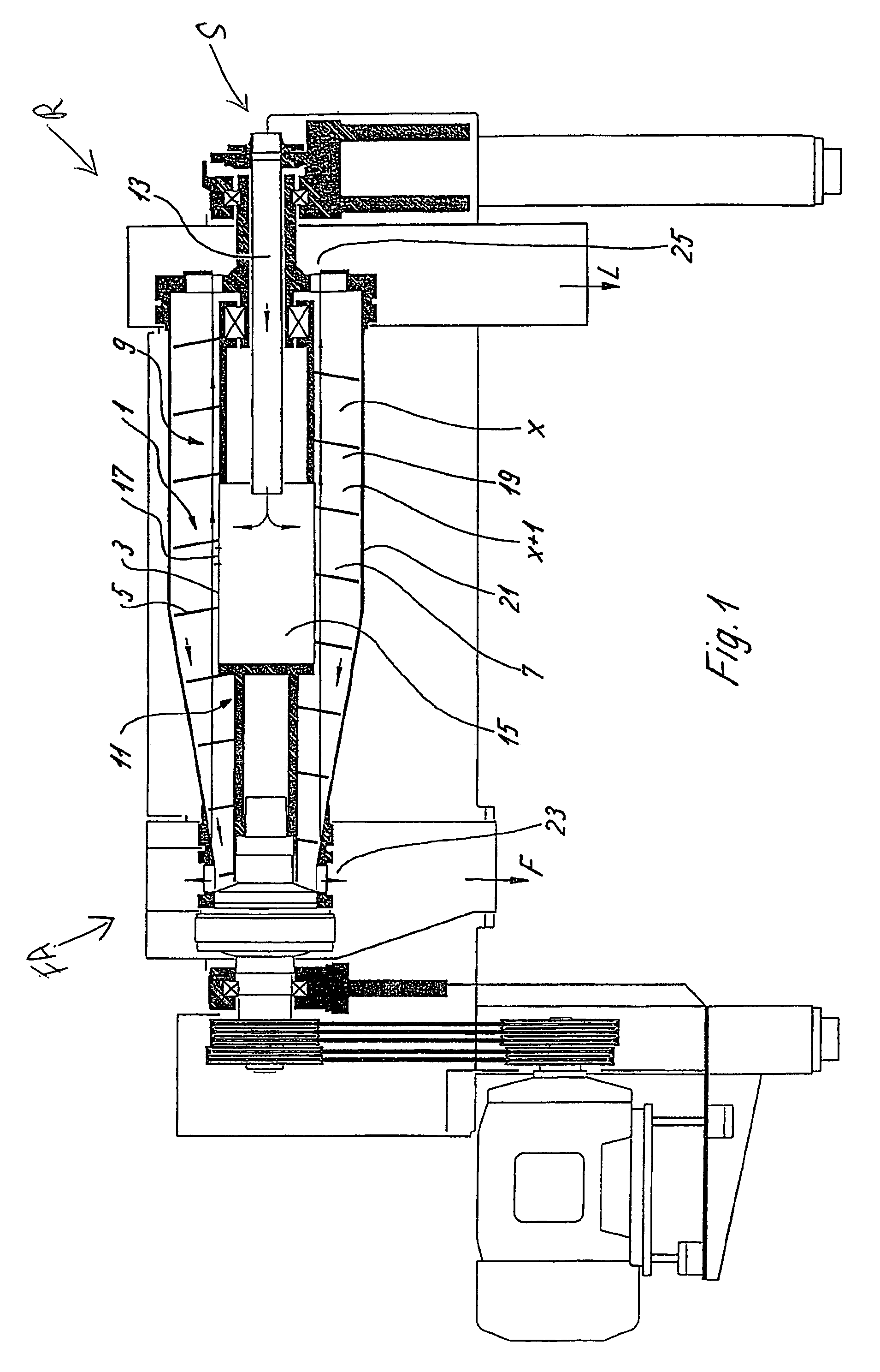
[0039]FIG. 1 illustrates a solid bowl screw centrifuge with a screw 1 which has a screw body 3 as well as, in this case, a screw blade 5 which surrounds the screw body 3 in a helical manner. Between the screw spirals x, x+1, . . . , a screw channel 7 is formed or constructed for conveying / transporting a material to be processed.

[0040]In a rear area R which is shown to the right when viewing FIG. 1, the screw body 3 has a cylindrical section 9 and, in a forward area FA, which adjoins area R, as seen in FIG. 1, the screw body 3 has a tapering section 11, which tapers in steps and which may, as an alternative, be conically shaped.

[0041]Material S to be centrifuged is guided through a centrally arranged inflow tube 13 into a distributor 15 and is then guided from there through radial openings 17 in the distributor 15 into a centrifuging chamber 19 of the screw 1. A drum 21 surrounds the screw 1.

[0042]The material S to be centrifuged is accelerated when passing through the distributor 15...


PUM


Abstract

The present invention relates to solid bowl screw centrifuge comprising a centrifuging chamber having a rotatable screw with a center axis and a rotatable drum surrounding the centrifuging chamber. Also included is an axially extending inflow tube for guiding material to be centrifuged into a distributor. The distributor is oriented in a substantially perpendicular manner with respect to the center axis of the screw and configured for introducing the material to be centrifuged into the centrifuging chamber. The distributor further includes at least one wall having a surface structure that includes projections configured such that a substantial portion of the material to be centrifuged flowing through the distributor must flow around at least one of the projections.

Description

BACKGROUND AND SUMMARY OF THE INVENTION[0001]The present invention relates to a solid bowl screw centrifuge having a rotating drum which surrounds a centrifuging chamber having a screw which also rotates. The centrifuge also has a distributor preferably constructed as a tube for introducing the material to be centrifuged into the centrifuging chamber. The distributor is oriented in an angular manner, particularly perpendicularly, with respect to the center axis of the screw, the material to be centrifuged being guided through an axially extending inflow tube into the distributor.[0002]In the case of solid bowl screw centrifuges, the material to be centrifuged is to be accelerated to the circumferential speed of the screw at the diameter of the liquid level (surface) in the screw channel. The relative velocity at the entry into the centrifuging chamber of the liquid surface is to be as low as possible.[0003]As a result of the acceleration to the circumferential speed of the screw at ...

Claims


Application Information

Patent Timeline
Patent Type & Authority Patents(United States)
IPC IPC(8): B04B1/20B04B11/06
CPCB04B1/20B04B11/06B04B2001/2033
Inventor HERMELER, JURGENBRUNING, PAULHORSTKOTTER, LUDGER
Owner WESTFALIA SEPARATOR AG
Learn More