
Vibratory compactor and compact exciter assembly usable therewith

Inactive Publication Date: 2006-06-13
WACKER NEUSON CORP
View PDF15 Cites 31 Cited by
  • Summary
  • Abstract
  • Description
  • Claims
  • Application Information

AI Technical Summary

Benefits of technology

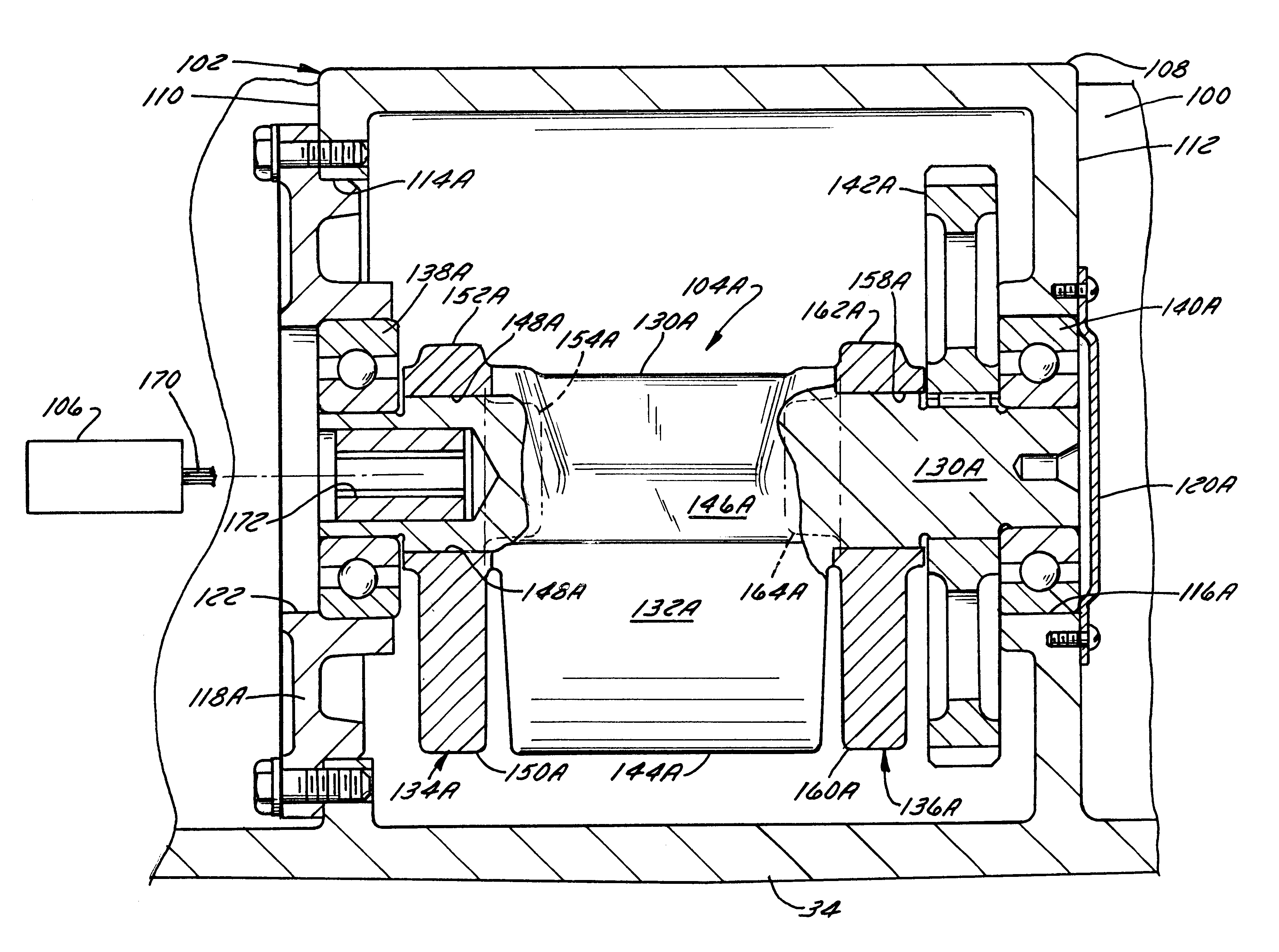
[0012]In accordance with a first aspect of the invention, an exciter assembly for a vibratory roller is provided that comprises an exciter housing, an exciter shaft rotatably journaled in the exciter housing, a fixed eccentric weight rotationally fixed to the exciter shaft, and at least one free swinging eccentric weight. The free swinging weight is mounted on the exciter shaft so as to rotate with respect to the exciter shaft between 1) a first angular position in which the eccentricity of the free swinging weight adds to the eccentricity of the fixed weight and 2) a second angular position in which the eccentricity of the free swinging weight detracts from the eccentricity of the fixed weight. The free swinging weight is mounted on the exciter shaft so as to be restrained from substantial axial movement along the exciter shaft without the use of any retaining structure that is fixed to the free swinging weight. The resultant exciter assembly is compact, lightweight, and easy to assemble.
[0016]In accordance with another aspect of the invention, a simple and easily implementable method of assembling an exciter assembly for a vibratory compactor comprises fixing a torque transfer element and at least two bearings to an exciter shaft, fixing an eccentric weight to the exciter shaft, mounting first and second free swinging eccentric weights on the exciter shaft adjacent respective ends of the fixed weight so as to be rotatable a limited amount relative to the exciter shaft, and restraining the first and second free swinging weights from substantial axial movement along the exciter shaft. The restraining step is advantageously performed solely by sandwiching the first and second free swinging weights between respective ends of the fixed weight and operative components of the exciter assembly, each of the operative components comprising one of a bearing and a torque transfer element.

Problems solved by technology

Rotation of the eccentric shaft imparts vibrations to the axle housing and to the remainder of the drum assembly.
First, it is relatively complicated and difficult to assemble.
These retainers substantially increase the overall complexity of the exciter, hindering assembly of the machine and increasing the exciter's cost.
Assembly is further hindered by the need to assemble at least part of the exciter within the drum assembly rather than as a separate subassembly that can be inserted into the axle housing as a unit.
The extra hardware required to mount the free swinging weights and other components of the exciter on the exciter shaft and / or to mount the exciter in the axle housing also substantially increases the weight of the exciter, thereby increasing its inertia.
The relatively high inertia undesirably increases exciter startup time.
Another problem associated with traditional exciter designs is that they are too lengthy to receive a coaxial motor when they are used on a vibratory trench roller.
Providing a longer axle housing is not an option because the permissible length of the axle housing is restricted by the width of the overall machine, which must be narrow enough to permit the trench roller to be placed inside a trench.
This requirement significantly increases the overall weight and complexity of the machine.
It also hinders access to hydraulic hoses and connections for the exciter drive motor, hindering motor repair and maintenance.

Method used


Image

  • Vibratory compactor and compact exciter assembly usable therewith
  • Vibratory compactor and compact exciter assembly usable therewith
  • Vibratory compactor and compact exciter assembly usable therewith

Examples


Embodiment Construction

1. Resume

[0029]Pursuant to the invention, a lightweight, easy to assemble, and compact exciter assembly is provided for a compaction device such as a drum assembly of a vibratory trench roller or another vibratory compactor. The exciter assembly includes a fixed weight and one or more free swinging weights mounted on an exciter shaft, without using any mounting hardware, so as to hold the free swinging weights axially in position while permitting them to swing between first and second angular positions on the exciter shaft. Preferably, the fixed weight is mounted on a central portion of the exciter shaft, and two free swinging weights are mounted adjacent the ends of the fixed weight so as to be restrained from substantial sliding movement along the exciter shaft solely by the fixed weight and other operative components of the exciter assembly such as bearings and / or gears or other torque transfer elements. The reduction in length afforded by this design permits a reversible hydraul...


PUM

PropertyMeasurementUnit
Weightaaaaaaaaaa

Abstract

A lightweight, easy to assemble, and compact exciter assembly for a compaction device such as a drum assembly of a vibratory trench roller or the like includes a fixed weight and one or more free swinging weights mounted on an exciter shaft, without using any mounting hardware, so as to hold the free swinging weights axially in position while permitting them to swing between first and second angular positions on the exciter shaft. Preferably, the fixed weight is mounted on a central portion of the exciter shaft, and two free swinging weights are mounted adjacent the ends of the fixed weight so as to be restrained from substantial sliding movement along the exciter shaft solely by the fixed weight and other operative components of the exciter assembly such as bearings and / or gears or other torque transfer elements. The reduction in length afforded by this design permits a reversible hydraulic motor to be mounted coaxially on the end of the exciter shaft without unacceptably increasing the overall length of a drum assembly, thereby further simplifying the machine's assembly and facilitating maintenance or repair of the machine.

Description

BACKGROUND OF THE INVENTION[0001]1. Field of the Invention[0002]The invention relates to a vibratory compactor used, e.g., to compact backfilled trenches after a pipeline is laid or to compact the floor of a trench prior to laying a pipeline and, more particularly, relates to a vibratory compactor of the above-mentioned type and having an easy to assemble, low inertia to compact exciter assembly. The invention additionally relates to an exciter assembly usable in a vibratory compactor and to a method of assembling the exciter assembly.[0003]2. Discussion of the Related Art[0004]Vibratory compactors are used in a variety of ground compaction and ground leveling applications. Most vibratory compactors have plates or rollers that rest on the surface to be compacted and that are excited to vibrate so as to compact and level the worked surface. A common vibratory compactor, and one to which the invention is well-suited, is a vibratory trench roller.[0005]The typical vibratory trench roll...

Claims


Application Information

Patent Timeline
IPC IPC(8): E01C19/28E02D3/026E02D3/032
CPCE01C19/286E02D3/026Y10T74/18552Y10T29/49826Y10T29/49696E02D3/032
Inventor GEIER, DANIELBRINKMANN, RONALDBAUDHUIN, JAY
Owner WACKER NEUSON CORP
Learn More