
Seal and bearing assembly

Inactive Publication Date: 2006-06-06
DUNRITE MFG CO
View PDF15 Cites 12 Cited by
  • Summary
  • Abstract
  • Description
  • Claims
  • Application Information

AI Technical Summary

Benefits of technology

[0019]Preferably, the ring defines a pair of substantially concentric annular grooves therein, and the first bearing race comprises a pair of annular portions, each of the portions extending into one of the grooves. Preferably, the annular portions are close, spaced from the bottom surfaces of the grooves to provide only minimal fluid leakage thereby, and the race engagement surface of the ring is between the grooves.

Problems solved by technology

A problem with the sealing in such equipment is that it is necessary to seal between a moving element connected to the rotating member and a stationary element connected to the housing.

Method used


Image

  • Seal and bearing assembly
  • Seal and bearing assembly
  • Seal and bearing assembly

Examples


first embodiment

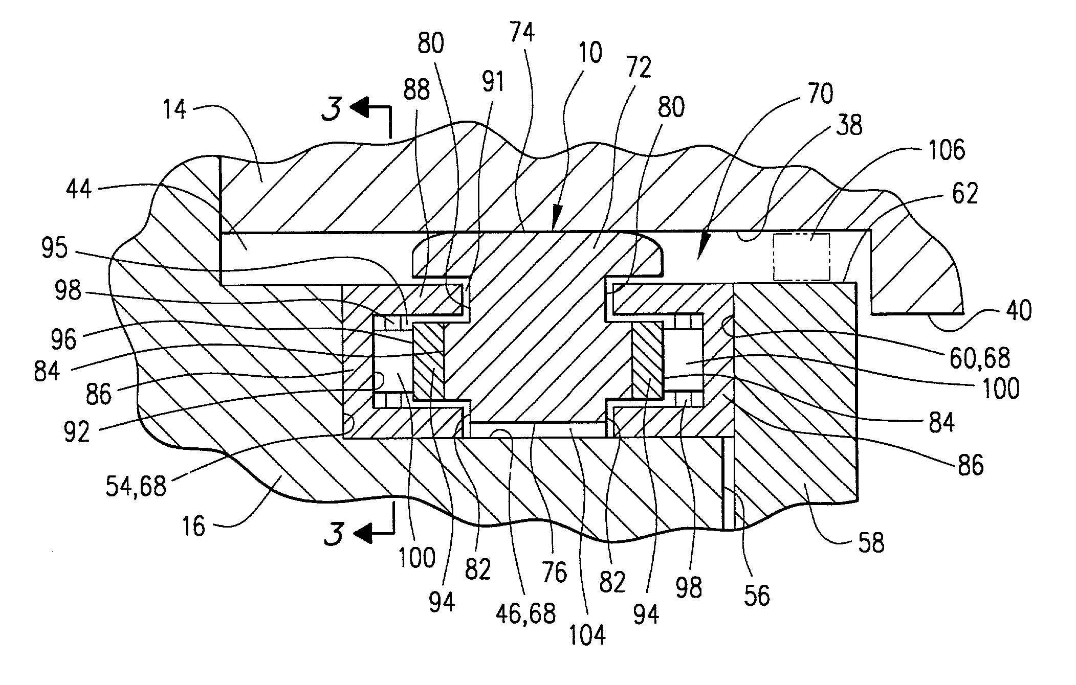
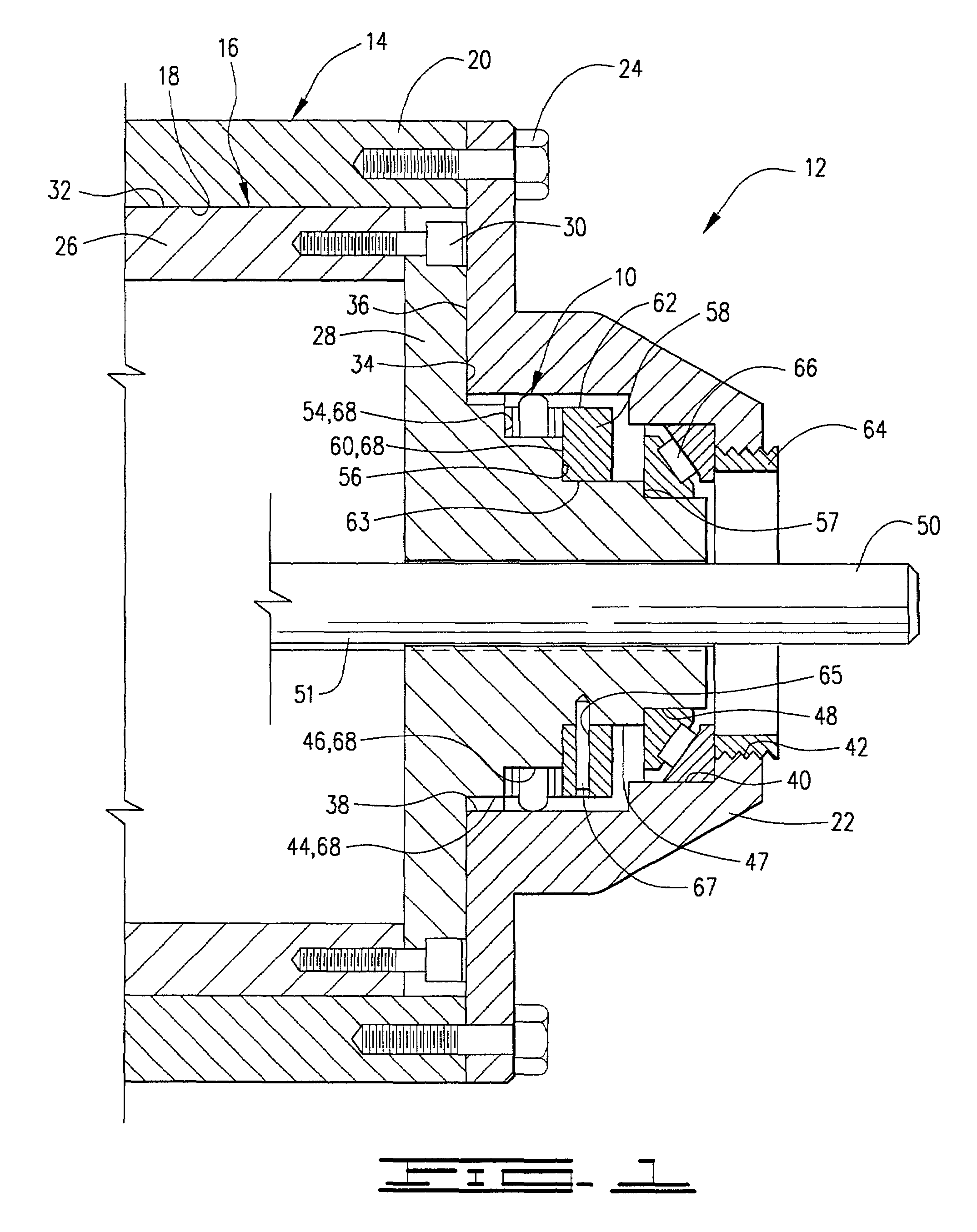
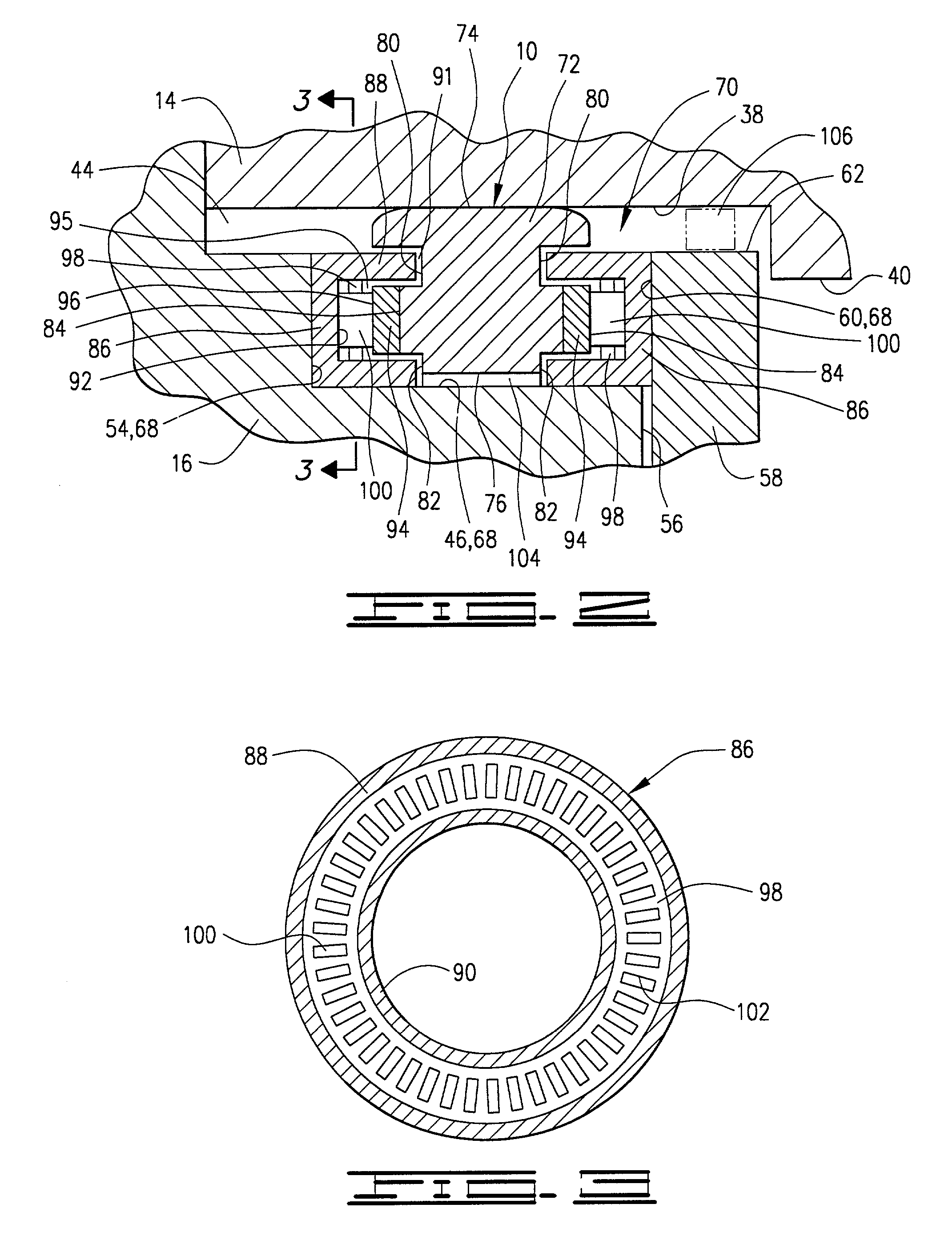
[0040]Referring now to FIGS. 2 and 3, details of first embodiment seal and bearing assembly 10 will be discussed.

[0041]Seal and bearing assembly 10 comprises a ring 72 having a sealing surface 74 sized to closely fit within stationary surface 38 preferably to form a metal-to-metal seal therebetween. Thus, ring 72 in the first embodiment is stationary. Ring 72 has an inner bore 76 defined therethrough which is radially spaced from second outside diameter 46.

[0042]Ring 72 defines also a pair of annular, outer grooves 80 on opposite sides thereof and a pair of annular, inner grooves 82 on opposite sides thereof. A radially extending race engagement surface 84 extends between grooves 82 and 80.

[0043]A first or outer race 86 is disposed between ring 72 and first shoulder 54 such that the first race substantially flatly contacts first shoulder 54. First race 86 has an outer annular portion 88 which extends into outer groove 80 and a substantially concentric inner annular portion 90 which ...

second embodiment

[0058]Details of second embodiment seal and bearing assembly 200 will now be discussed.

[0059]Seal and bearing assembly 200 comprises a first or outer race 244, a second or outer race 246 and a bearing cage 248 disposed between the first and outer races. Bearing cage defines a plurality of bearing openings 250 therein, and a plurality of bearing elements 252 are disposed in the bearing openings. These components of second embodiment seal and bearing assembly 200 are substantially identical to first race 86, second race 94, bearing cage 98 and bearing elements 100 of first embodiment seal and bearing assembly 100.

[0060]First race 244 has an outer annular portion 254 which extends into outer groove 236 and a substantially concentric inner annular portion 256 which extends into inner groove 238 without contacting the bottoms of the grooves. Annular portions 254 and 256 and grooves 236 and 238 are sized such that a narrow gap 258 is defined therebetween. Gap 258 is sized to provide for a...


PUM


Abstract

A seal and bearing assembly for use in rotating machinery of the type having a rotor which turns within a stationary housing. The rotor and housing define a seal cavity therein in which the seal and bearing assembly is positioned. The assembly comprises a first bearing race adapted for engagement with a rotating surface on the rotor or a stationary surface, a second race adapted for engagement with the other of the rotating or stationary surfaces, and a plurality of bearing elements disposed between the first and second races. A bearing cage may be used which defines a plurality of bearing openings therein disposed between the first and second races, wherein the bearing elements are disposed in the bearing openings. Preferably, the bearing elements are rollers. In one embodiment, the seal and bearing assembly also comprises a ring that substantially seals along the stationary surface in the housing, wherein the ring defines a race engagement surface thereon, the first bearing engages the rotating surface, and the second race engages the race engagement surface. In a preferred embodiment, the assembly has first races on opposite sides of the ring with corresponding second races and bearing elements and / or cages. The bearing components are sized such that any fluid flow or leakage therethrough is minimal.

Description

BACKGROUND OF THE INVENTION[0001]1. Field of the Invention[0002]This invention relates to seals used in rotating machinery, and more particularly, to a seal assembly having a seal ring supported by one or more bearings and having a minimal fluid flow or leakage path therethrough.[0003]2. Brief Description of the Prior Art[0004]The use of seals and bearings in rotating machinery is well-known. An example of this kind of machinery is one which has a housing with a rotating member disposed therein. Such rotating members frequently have shafts or axles extending therefrom, and bearings are used to support the shafts while allowing rotation of the shaft and rotating member within the housing. Examples of such devices are pumps, turbines, etc. A variety of seals are used in these to keep fluid in the housing.[0005]A problem with the sealing in such equipment is that it is necessary to seal between a moving element connected to the rotating member and a stationary element connected to the ...

Claims


Application Information

Patent Timeline
IPC IPC(8): F16J15/34F16C19/10F16C19/30F16C33/76F16C33/78F16C33/80F16J15/16
CPCF16C33/76
Inventor STEWART, JR., LANDS J.
Owner DUNRITE MFG CO
Learn More