
Vascular clamps for vascular repair

a technology for vascular repair and clamps, applied in the field of surgical devices, can solve problems such as damage or compromise of vessels, and achieve the effect of minimising fluid leakag

Inactive Publication Date: 2013-02-26
MED EL ELEKTROMEDIZINISCHE GERAETE GMBH
View PDF7 Cites 0 Cited by
  • Summary
  • Abstract
  • Description
  • Claims
  • Application Information

AI Technical Summary

Benefits of technology

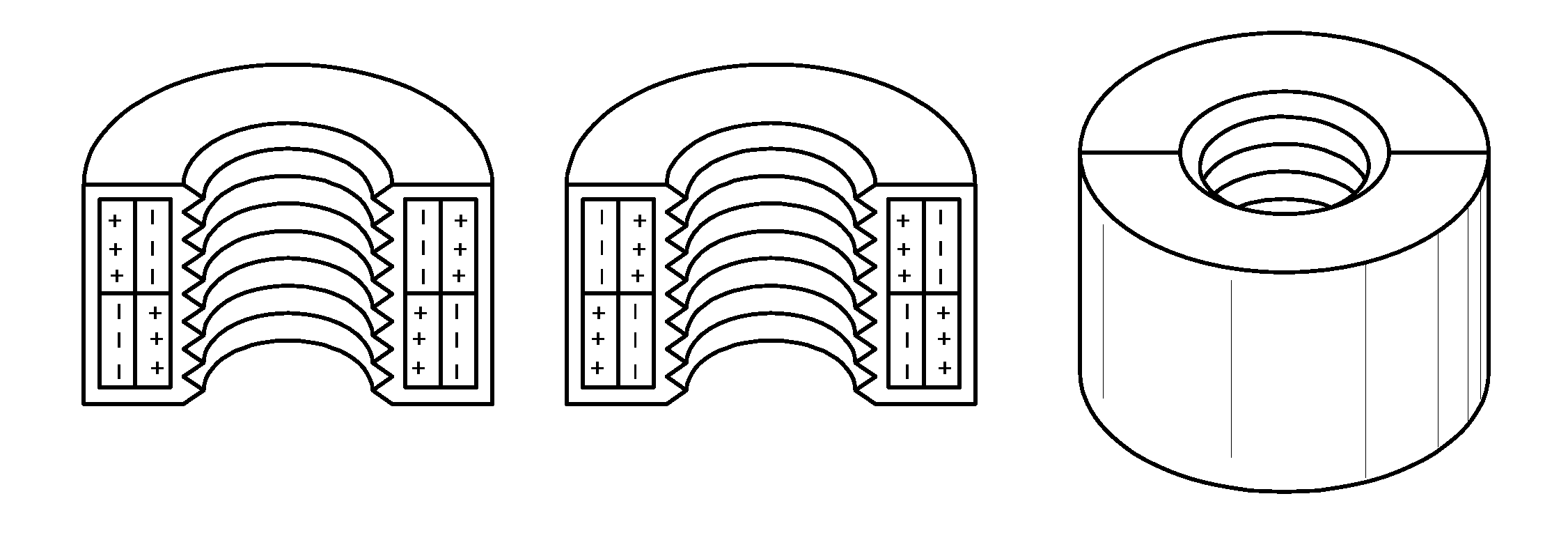
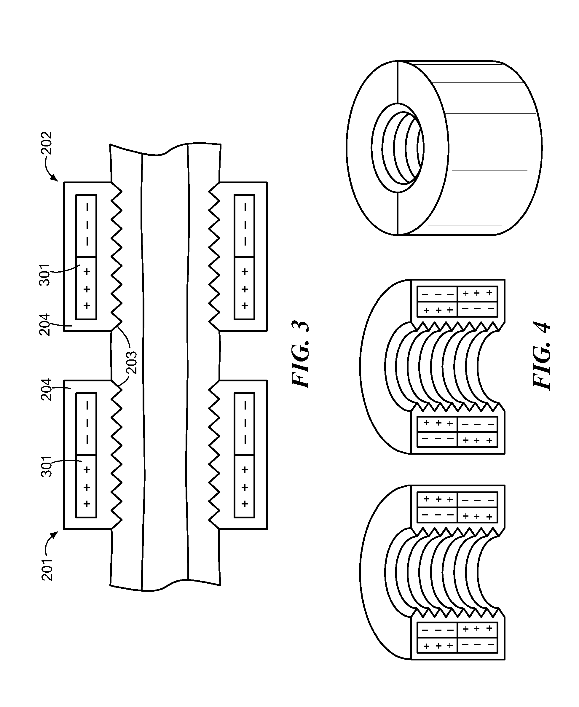
[0004]Embodiments of the present invention are directed to a magnetic vascular clamp for vascular repair. There are two clamp pieces, where each clamp piece forms a partial cylindrical section of an annular cylinder. Each clamp piece has an outer surface and an inner surface, structural ribs arranged across the inner surface from one sectional end to the other, and a pair of magnetic sectional end surfaces connecting the outer surface and the inner surface and having a characteristic magnetic field arrangement. The sectional end surfaces and magnetic field arrangements of each clamp piece cooperate with the sectional end surfaces and magnetic field arrangements of the other clamp piece to form a complete annular cylinder held together by the magnetic field arrangements and enclosing an inner cylinder so as to structurally support damaged vascular tissue therein with minimal fluid leakage.
[0009]Embodiments of the present invention also include a vascular clamp for vascular repair which has a vascular sleeve which forms a flexible cylindrical bellows that cylindrically encloses a section of vascular tissue to allow freely movement of the enclosed vascular tissue within the vascular sleeve. At each cylindrical end of the vascular sleeve there is a sleeve anchor ring that forms a fixed seal with underlying vascular tissue to minimize fluid leakage from within the vascular clamp.

Problems solved by technology

These vessels can become damaged or compromised, for example, due to injury-related trauma or during surgical procedures.

Method used


Image

  • Vascular clamps for vascular repair
  • Vascular clamps for vascular repair
  • Vascular clamps for vascular repair

Examples


Embodiment Construction

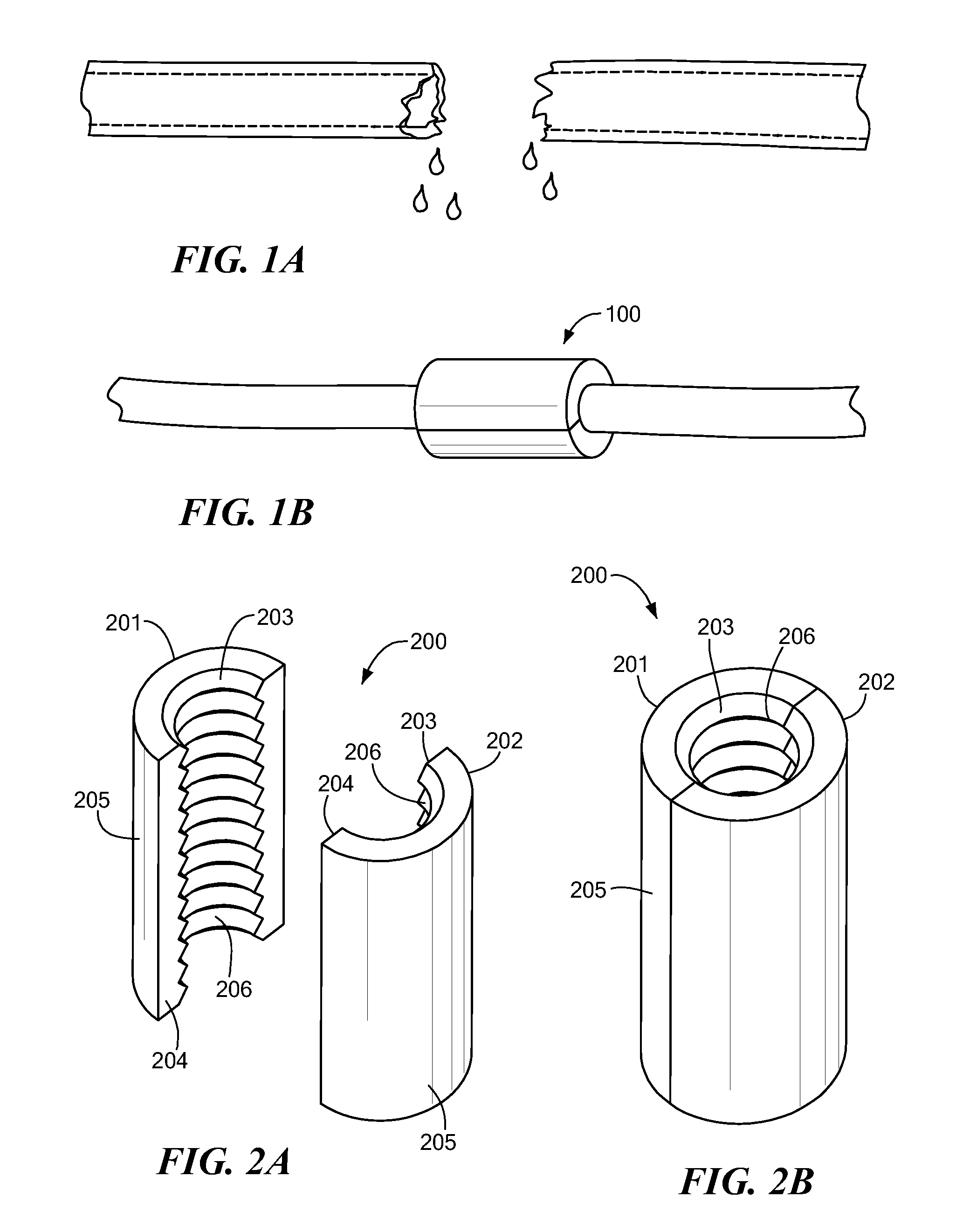
[0020]Embodiments of the present invention are directed to a various vascular clamp devices for vascular repair. As shown in FIG. 1A, a damaged blood vessel allows blood to leak out from within. A vascular clamp 100 fits over the damaged section of blood vessel as shown in FIG. 1B to occlude blood flow and support the structure of the enclosed vascular tissue.

[0021]FIG. 2 A-B shows elevated perspective views of the structure of a magnetic vascular clamp 200 according to one embodiment. There are two clamp pieces 201 and 202 each of which forms a partial cylindrical section of an annular cylinder. Each clamp piece 201 and 202 has an outer surface 205 and an inner surface 203 across which are arranged a plurality of structural ribs 206 from one sectional end to the other.

[0022]Each clamp piece 201 and 202 also has a pair of magnetic sectional end surfaces 204 connecting the outer surface 205 and the inner surface 203 and having a characteristic magnetic field arrangement 301 as shown ...


PUM


Abstract

A magnetic vascular clamp for vascular repair is described. There are two clamp pieces, where each clamp piece forms a partial cylindrical section of an annular cylinder. Each clamp piece has an outer surface and an inner surface, structural ribs arranged across the inner surface from one sectional end to the other, and a pair of magnetic sectional end surfaces connecting the outer surface and the inner surface and having a characteristic magnetic field arrangement. The sectional end surfaces and magnetic field arrangements of each clamp piece cooperate with the sectional end surfaces and magnetic field arrangements of the other clamp piece to form a complete annular cylinder held together by the magnetic field arrangements and enclosing an inner cylinder so as to structurally support damaged vascular tissue therein with minimal fluid leakage.

Description

[0001]This application claims priority from U.S. Provisional Application 61 / 306,689, filed Feb. 22, 2010; incorporated herein by reference.FIELD OF THE INVENTION[0002]The present invention relates to surgical devices, and more specifically to devices for use in repairing vascular structures in a patient.BACKGROUND ART[0003]Blood vessels are the body's equivalents of pipes for circulating blood to where it is needed. These vessels can become damaged or compromised, for example, due to injury-related trauma or during surgical procedures. Vascular clamps are devices that surround damaged vascular tissue to provide structural support while minimizing blood loss while repair surgery is performed.SUMMARY OF THE INVENTION[0004]Embodiments of the present invention are directed to a magnetic vascular clamp for vascular repair. There are two clamp pieces, where each clamp piece forms a partial cylindrical section of an annular cylinder. Each clamp piece has an outer surface and an inner surfa...

Claims


Application Information

Patent Timeline
Patent Type & Authority Patents(United States)
IPC IPC(8): A61B17/08A61F2/06
CPCA61B17/0057A61B17/1114A61B17/122A61F2/064A61B17/08A61B2017/00876A61B2017/1107A61B2017/12004A61F2210/009
Inventor BALL, GEOFFREY R.
Owner MED EL ELEKTROMEDIZINISCHE GERAETE GMBH
Learn More