Eureka AIR delivers breakthrough ideas for toughest innovation challenges, trusted by R&D personnel around the world.

Panel arrangement

a technology of space-dividing wall panels and panels, which is applied in the direction of walls, carriage/perambulator accessories, transportation and packaging, etc., can solve the problems of limited cabling capacity, difficult to accommodate all of the power and telecommunication cabling for all workstations associated with a particular group of workstations, and difficult reconfiguration of workstations

Inactive Publication Date: 2006-06-06
PNC BANK NAT ASSOC AS ADMINISTATIVE AGENT
View PDF17 Cites 30 Cited by
  • Summary
  • Abstract
  • Description
  • Claims
  • Application Information

AI Technical Summary

Benefits of technology

[0012]It is another object of the invention to provide wall panels and in particular, base panels supported on the floor which have an increased load-bearing capacity so as to accommodate the furniture components of a large number of workstations. It is an object that such load-bearing capacity readily handle the loads associated with the individual furniture components supported on the base panel, as well as the loads transferred thereto by return walls which are connected to the base panel and are loaded with their own furniture components and equipment.
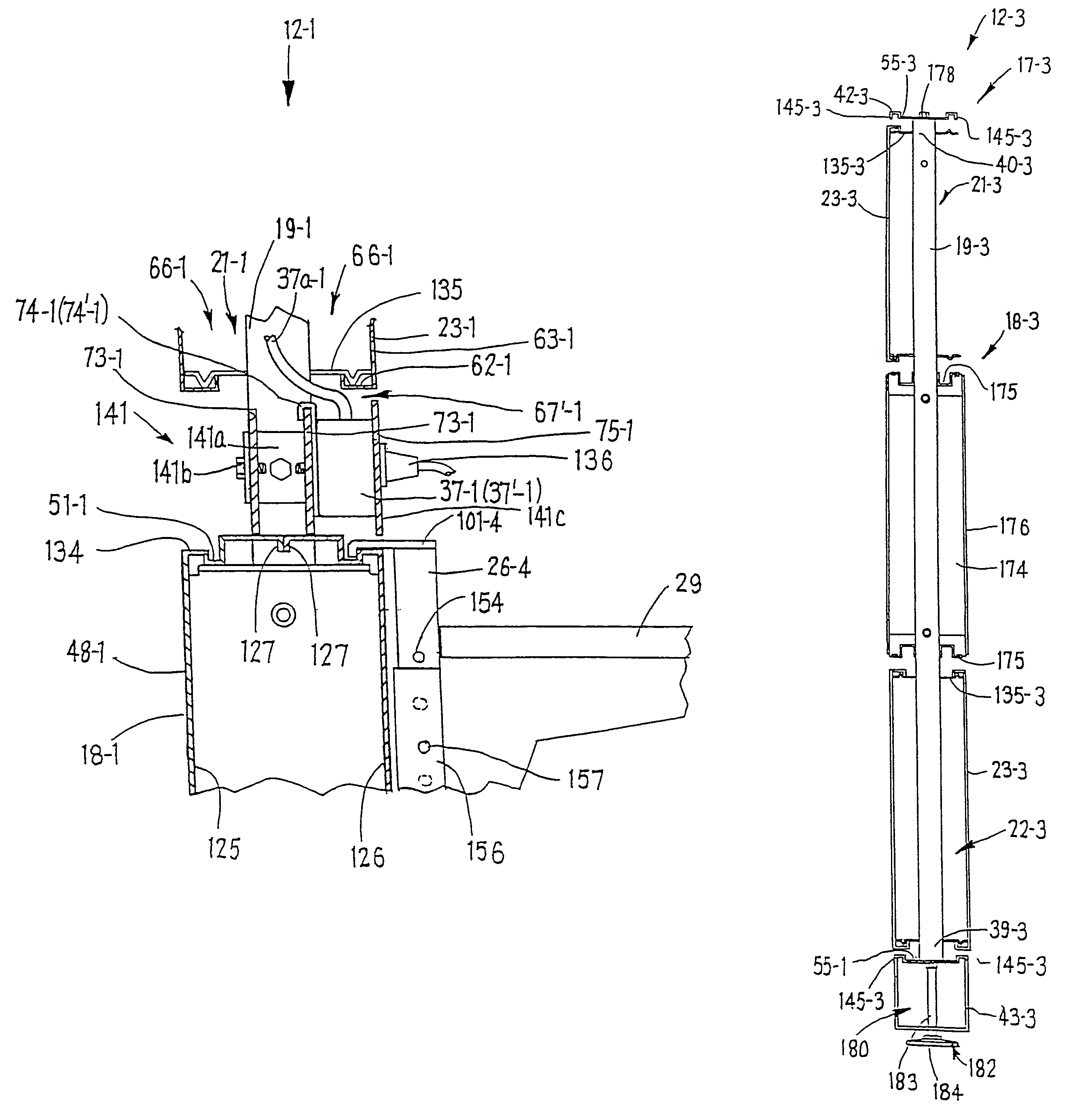
[0015]To permit the connection of furniture components, the box-beam as well as the cross rails are formed with longitudinally extending horizontal channels, which channels are positioned outwardly of the uprights on the opposite sides thereof. The channels are free of interference with the vertical uprights while extending to the opposite ends of the base panel to thereby align with corresponding channels on a serially-adjacent base panel. The aligned channels define a continuous linear track preferably along the entire linear length of the spine wall system. The channels or more specifically, the tracks accommodate appropriate mounting hooks of furniture components such as return walls to fixedly secure the components to the base panel while permitting continuous, uninterrupted sliding or adjustment of the furniture components along the entire linear length of the track. Such an arrangement thus provides continuous off-modularity for the furniture components including the return walls.

Problems solved by technology

In such an arrangement, however, the wall panels typically have a relatively narrow thickness to minimize the floor space being used and thereby have a limited cabling capacity.
As a result, it may become difficult to accommodate all of the power and telecommunication cabling for all of the workstations associated with a particular group of workstations.
This arrangement, however, requires the removal of furniture components when moving these components between panels and also routes horizontal cabling through the posts which thereby makes reconfiguration of workstations more difficult.

Method used


Image

  • Panel arrangement
  • Panel arrangement
  • Panel arrangement

Examples


Embodiment Construction

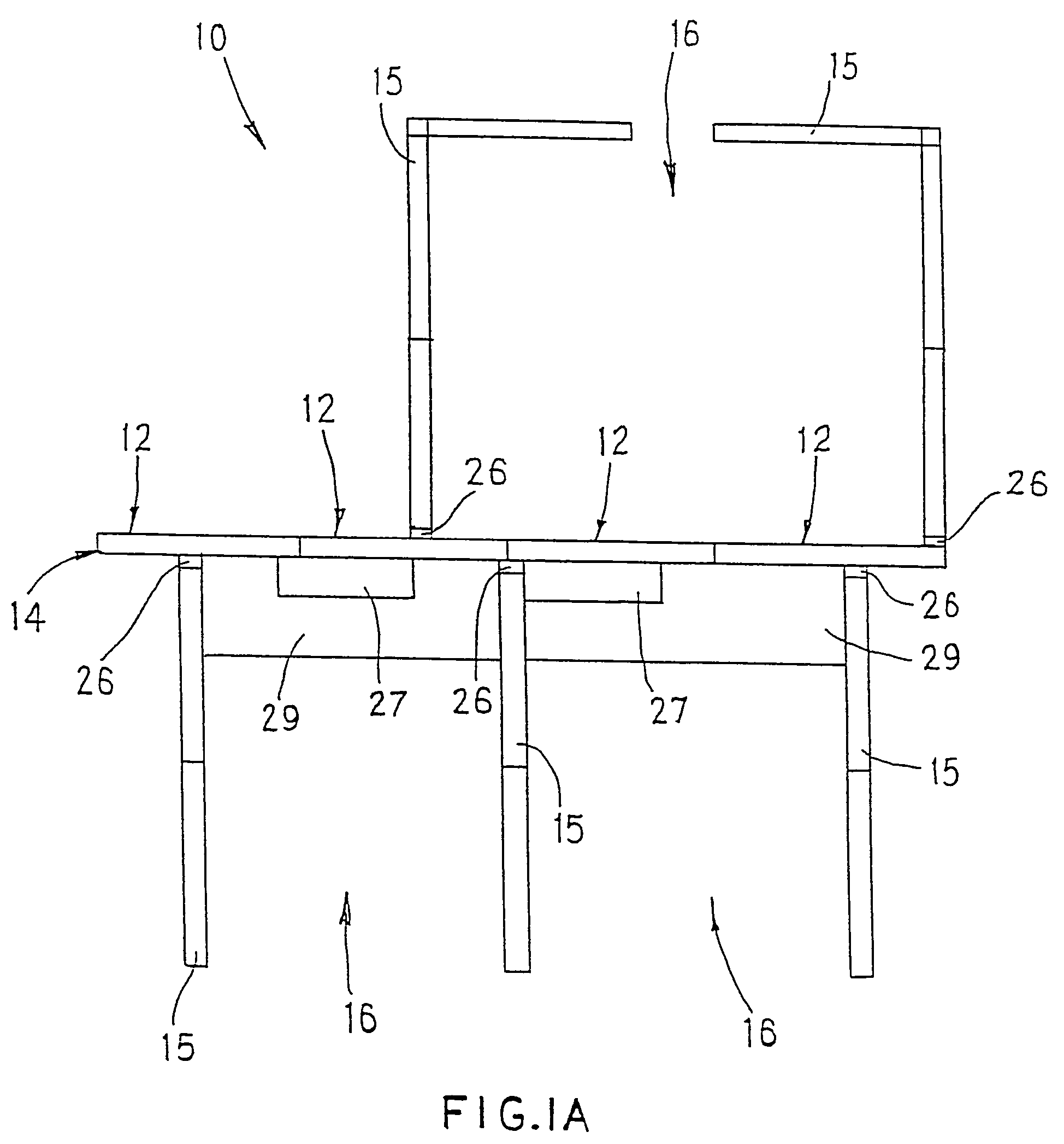
[0060]Referring to FIGS. 1A and 1B, the invention generally relates to a space-dividing wall panel system 10 for subdividing an office area. The wall panel system 10 includes a selected number of upstanding wall panel assemblies 12 horizontally serially connected, for example, in straight configurations so as to define a primary space-dividing wall 14 having substantial load-bearing and cable-carrying capacities. The wall 14 is commonly referred to as a “spine wall”, and typically is provided in combination with return walls 15 for subdividing the office area into separate workstations 16.

[0061]To accommodate substantial loads and cabling, the wall panel assemblies 12 of the invention include base panels 17 (FIGS. 5 and 6A) which each include an enlarged horizontally extending box-like cross beam 18 connected between vertical uprights 19. The base panels 17 define horizontal raceways 21 and 22 (FIG. 5) respectively above and below the box-beam 18, which raceways are enclosed by remo...


PUM


Abstract

This invention relates to a space-dividing wall panel system having a plurality of base panels which are serially connectable one with the other to define a vertically enlarged wall supported on a floor. Each base panel is defined by at least one horizontal box-beam rigidly connected to a pair of laterally spaced apart vertical uprights which are connected at the opposite ends of the box-beam and have a reduced thickness compared thereto. With this clearance between the faces of the box-beam and the uprights, the box-beam, cross rails at the ends of the uprights as well as additional extension panels are formed with longitudinally extending channels which are positioned free of interference with the vertical uprights and aligned with serially-adjacent channels of serially-adjacent wall panels. The channels provide a continuous linear track on the opposite sides of the upright which permit the connection of mounting hooks of furniture components and permit continuous, uninterrupted sliding or adjustment of the furniture components along the entire length of the aligned channels.

Description

[0001]This is a continuation of U.S. Ser. No. 09 / 659,432, filed Sep. 8, 2000, now U.S. Pat. No. 6,658,805 which is a division of U.S. Ser. No. 09 / 220,169, filed Dec. 23, 1998, now Patent No. 6,161,347, which is a continuation of U.S. Ser. No. 08 / 736,512, filed Oct. 24, 1996, now U.S. Pat. No. 5,852,904, which is a continuation-in-part of U.S. Ser. No. 08 / 692,344, filed Aug. 5, 1996, now abandoned.FIELD OF THE INVENTION[0002]This invention relates to a space-dividing wall panel system formed from upright panels and, more specifically, to a wall panel system defining an improved load-bearing and cable-carrying “spine” wall to which return walls are connected to define individual workstations.BACKGROUND OF THE INVENTION[0003]Commercial buildings typically include large open office areas which are divided into smaller work spaces or workstations by any of a number of space divider and panel systems that have been developed therefor. These space divider arrangements typically employ upri...

Claims


Application Information

Patent Timeline
IPC IPC(8): E04C2/52E04C2/34E04B2/74
CPCE04B2/7422E04B2002/7462E04B2002/749E04B2002/7487E04B2002/7488E04B2002/7483
Inventor YU, X. SHAWNGINGRICH, BRYAN R.TUTTLE, ROBERT L.FOCO, KEITH
Owner PNC BANK NAT ASSOC AS ADMINISTATIVE AGENT
Why Eureka
Eureka Blog
Learn More