Apparatus for monitoring polarization-mode dispersion and chromatic dispersion and transmitting means for transmitting optical signal in optical network

a technology of optical network and optical signal, applied in the direction of transmission, transmission monitoring, electromagnetic transmission, etc., can solve the problems of affecting the quality of optical signals, aggravate transmission quality, and polarization-mode dispersion and chromatic dispersion are ever becoming serious problems

Inactive Publication Date: 2006-05-30
TERALINK COMM CO LTD
View PDF6 Cites 6 Cited by
  • Summary
  • Abstract
  • Description
  • Claims
  • Application Information

AI Technical Summary

Problems solved by technology

In high-speed optical networks, optical signal distortion due to the polarization-mode dispersion and the chromatic dispersion occurring in an optical fiber affects the quality of optical signals.
The polarization-mode dispersion limits the allowable maximum transmission distance and aggravates transmission quality by causing expansion of pulse width of the light signal being modulated into the square wave along with the chromatic dispersion in optical transmission systems.
Polarization-mode dispersion and chromatic dispersion are ever becoming a serious problem as the networks demand larger capacity and higher speed.
Also, the polarization-mode dispersion of optical fiber undergoes stochastic changes due to fiber's structural incompleteness, pinch, bending, twist, pressure, temperature, etc.
This much probability can cause a little bit of penalty to a system with channel transmission rate of 2.5 Gb / s when existing fibers with a large polarization-mode dispersion is used for a long transmission distance of 640 km.
It can also cause a little bit of penalty to a system using currently available low polarization-mode dispersion fiber if the channel transmission rate reaches 40 Gb / s.
But these methods are unable to monitor the polarization-mode dispersion value of the optical signal when it passes through various optical fibers.
So far, no methods of monitoring polarization-mode dispersion for these cases have been disclosed.
Accordingly, the methods in the prior art could not discern other factors such as chromatic dispersion which affects distortion of optical signals.
Consequently, the monitoring methods in the prior art were not able to discern the optical signal distortion caused by polarization-mode dispersion from that by chromatic dispersion.

Method used


Image

  • Apparatus for monitoring polarization-mode dispersion and chromatic dispersion and transmitting means for transmitting optical signal in optical network
  • Apparatus for monitoring polarization-mode dispersion and chromatic dispersion and transmitting means for transmitting optical signal in optical network
  • Apparatus for monitoring polarization-mode dispersion and chromatic dispersion and transmitting means for transmitting optical signal in optical network

Examples


Embodiment Construction

[0020]Hereinafter, the present invention is described in detail through preferred embodiments by referring to the accompanying drawings.

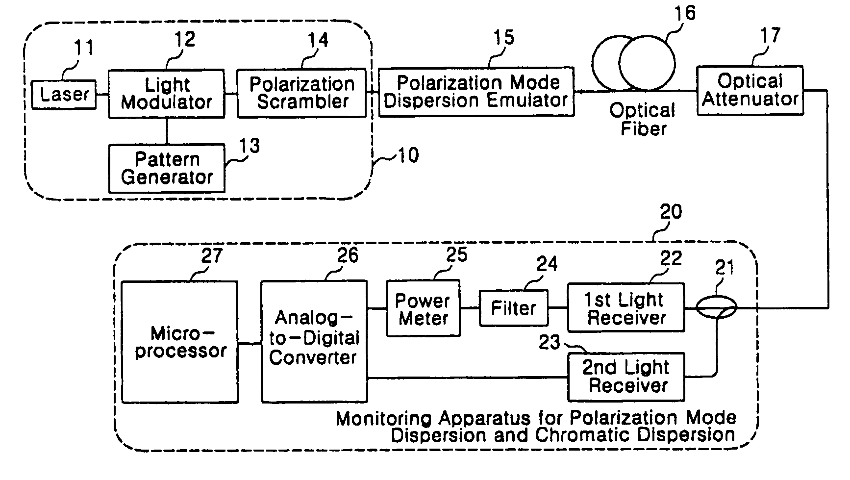
[0021]FIG. 1 is a diagram illustrating the configuration of a monitoring apparatus in accordance with the present invention and illustrates generally how the apparatus is constituted to monitor optical signals for their polarization-mode dispersion and chromatic dispersion.

[0022]The constitution of FIG. 1 is composed, in a broad sense, of a transmitting means (10) for transmitting data in the form of optical signals through an optical fiber and a monitoring device (20) for monitoring the optical signals for their polarization-mode dispersion and chromatic dispersion after photoelectric conversion thereof.

[0023]The transmitting means (10) in the present invention is similar in its function to that in the prior art, but further comprise a polarization scrambler (14) adopting the polarization scrambling technique that allows the transmitting optical si...


PUM


Abstract

An apparatus for monitoring polarization-mode dispersion and chromatic dispersion in optical networks in accordance with the present invention comprises; an optical distributor for distributing input optical signals, a first light receiver for photoelectrically converting the optical signals distributed by the distributor, a second light receiver for photoelectrically converting the optical signals to measure the average power of the optical signals distributed by the distributor, a filter for filtering output signals from the first light receiver, a power meter for measuring the frequency band of the optical signals filtered by the filter, an analog-to-digital (A / D) converter for converting the analog signals from the first and the second receivers into digital signals, a microprocessor for monitoring the polarization-mode dispersion and the chromatic dispersion of the optical signals by means of the digital signals from the A / D converter, and further a polarization scrambler in the optical signal sending-end.

Description

BACKGROUND OF THE INVENTION[0001]1. Field of the Invention[0002]The present invention relates to an apparatus for monitoring optical signal performance for operation / maintenance / management of optical communication networks. More particularly, the invention relates to a monitoring apparatus detecting optical signal distortions due to polarization-mode dispersion and chromatic dispersion and indicating the magnitudes of polarization-mode dispersion and chromatic dispersion by means of measuring the power over the signal frequency band of interest and using the polarization scrambling technique at the sending-end.[0003]2. Description of the Related Art[0004]Wavelength division multiplexing (WDM) scheme based optical networks are efficient high-speed broadband networks that transmit high-speed optical signals by allocating a plurality of wavelengths on one communication channel. In the recent information society, as demand for various kinds of data services such as Internet and high-qua...

Claims


Application Information

Patent Timeline
Patent Type & Authority Patents(United States)
IPC IPC(8): H04B10/08H04B17/00H04B10/077H04B10/079H04B10/2513H04B10/2569
CPCH04B10/077H04B10/07951H04B10/2569H04B10/2513H04B10/07955H04B10/07
Inventor CHUNG, YEUN-CHOLPARK, KEUN-JUKIM, HUNLEE, JUN-HEANGYUN, CHUN-JUSHIN, SEUNG-KYUN
Owner TERALINK COMM CO LTD
Why Eureka
Try Eureka