
System and method for monitoring alignment of a signal lamp

a technology for monitoring and alignment of signals, applied in the field of signal lamps, can solve the problems of not being seen, cost involved in performing inspections, and expensive to send maintainers out to the many sites for inspections

Inactive Publication Date: 2006-05-30
GENERAL ELECTRIC CO
View PDF6 Cites 19 Cited by
  • Summary
  • Abstract
  • Description
  • Claims
  • Application Information

AI Technical Summary

Benefits of technology

Enables periodic and automated monitoring of signal lamp alignment, reducing costs and response time, improving safety by promptly addressing misalignment issues and minimizing human error.

Problems solved by technology

If the lamps are misaligned, then they may not be seen until it is too late to avoid a dangerous situation.
A problem with manually inspecting the alignment of the signal lamps is the cost involved with performing the inspection.
In particular, it is expensive to send a maintainer out to the many sites to do an inspection on a yearly or monthly basis.
Moreover, the response time to correct a misaligned lamp is limited by the frequency of manual inspection or notification by passing motorists.
Another problem is that of human error with maintenance of signal alignment with the roadway.
As a result, alignment problems could be reported as they occur and fixed very soon thereafter.

Method used


Image

  • System and method for monitoring alignment of a signal lamp
  • System and method for monitoring alignment of a signal lamp
  • System and method for monitoring alignment of a signal lamp

Examples


Embodiment Construction

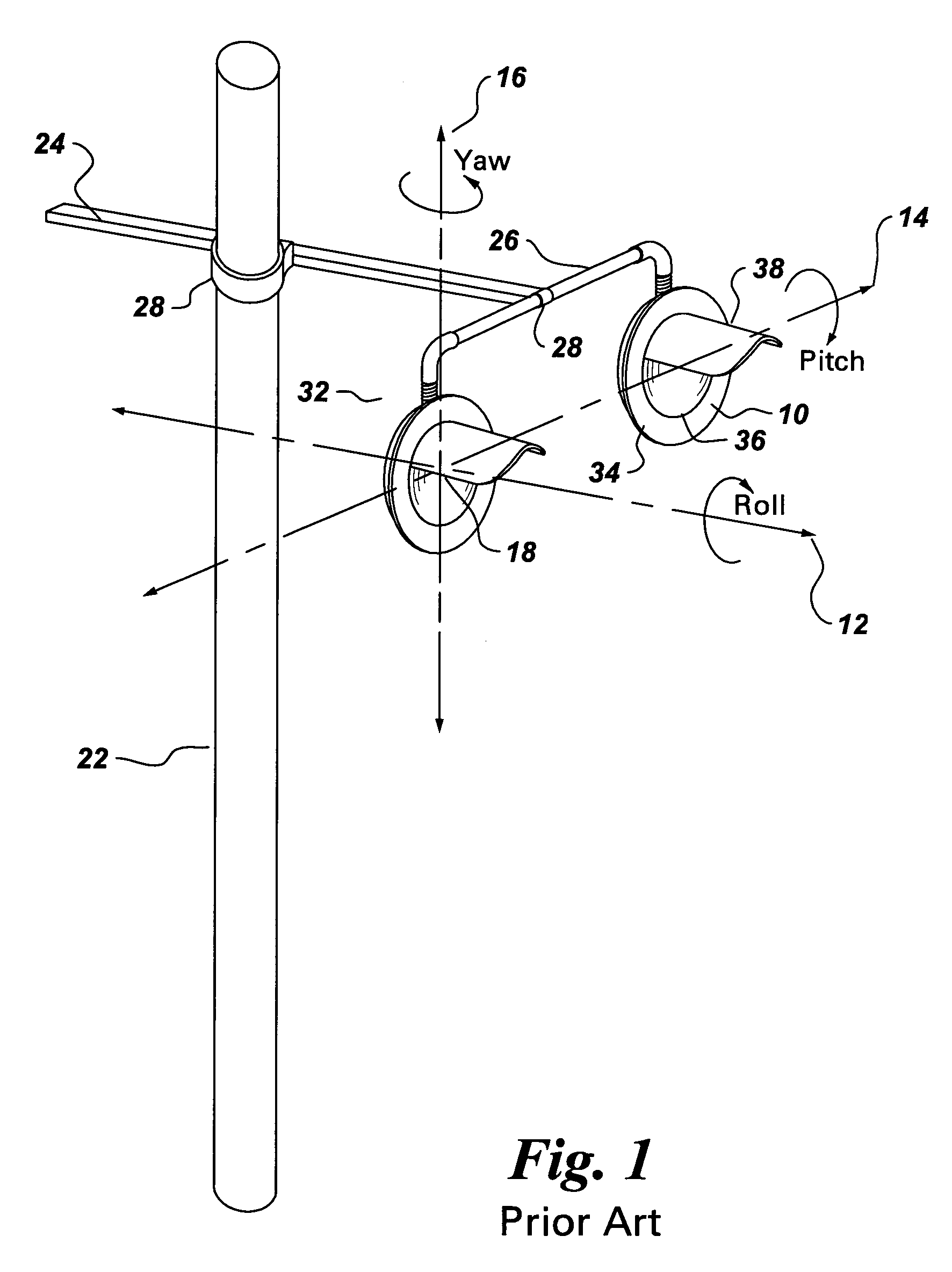
[0015]FIG. 1 illustrates a common signal lamp 10 that is in place in many highway-rail grade crossings or road-road crossings. Although the present invention is described with reference to a signal lamp found at a highway-rail grade crossing, the principles of the invention are not limited to such signal lamps. One of ordinary skill will recognize the invention is suited for other types of signal lamps such as traffic signal lamps composed of a plurality of lamps each having a single color or symbol that are generally installed at intersection approaches in order to control the flow of automobiles and pedestrians.

[0016]In addition to showing the signal lamp, FIG. 1 illustrates the lamp's supporting structure and all its possible axes of movement. The supporting structure comprises a vertical mast 22, a horizontal bar 24, horizontal arms 26 and a coupling fixture 32. The horizontal bar 24 is fixed to the mast 22 by means of an interlocking mechanism 28. The horizontal arms 26 and the...


PUM


Abstract

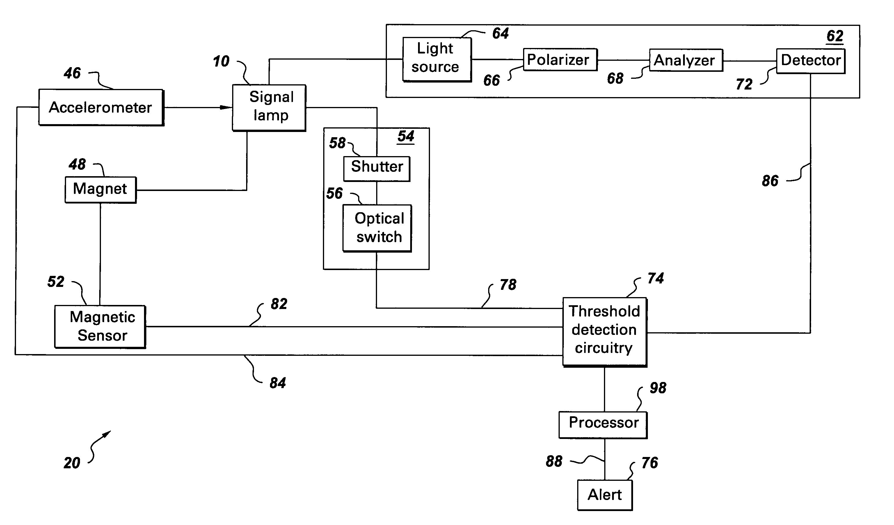
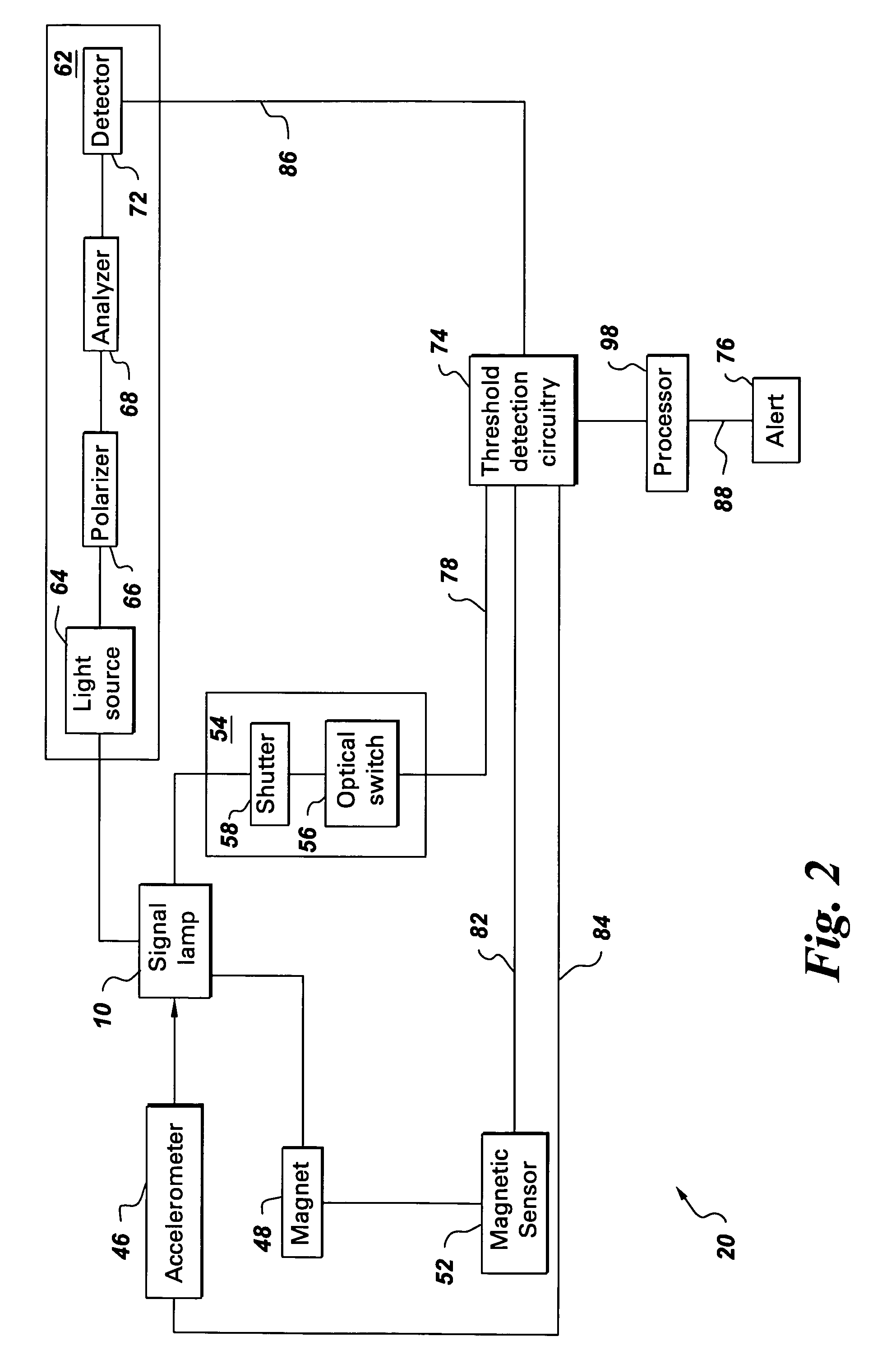
A system for monitoring alignment of a signal lamp includes at least one sensor and threshold detection circuitry. The sensor is positioned about the signal lamp and is configured to measure at least one of azimuthal and elevational movement of the signal lamp and generate an electrical signal. The threshold detection circuitry is configured to receive signals representative of the azimuthal and elevational movement of the signal lamp from the sensor. The threshold detection circuitry determine a change in alignment of the signal lamp according to at least one of the azimuthal movement signals and the elevational movement signals.

Description

BACKGROUND OF THE INVENTION[0001]The present invention generally relates to signal lamps and more particularly to a system and method for monitoring alignment of a signal lamp.[0002]Signal lamps are a common means of warning and controlling approaching traffic at a highway-rail grade crossing or road-road crossing. A typical signal lamp utilizes alternating flashing lamps to warn oncoming traffic of an approaching vehicle or a train. When properly aligned, the flashing lamps are highly visible to motorists approaching the crossing. If the lamps are misaligned, then they may not be seen until it is too late to avoid a dangerous situation.[0003]Usually a signal lamp unit is inspected when installed and then periodically for proper alignment and frequency of flashes in accordance with installation specifications. Currently, signal lamps are inspected for alignment by sending a signal lamp maintainer out to each site and manually checking the alignment of each lamp. A problem with manua...

Claims


Application Information

Patent Timeline
Patent Type & Authority Patents(United States)
IPC IPC(8): G08B21/00B61L5/18
CPCB61L5/1881B61L5/1863
Inventor HATFIELD, WILLIAM THOMASWELLES, II, KENNETH BRAKELEYMATHEWS, JR., HARRY KIRKANDARAWIS, EMAD ANDARAWISDAVENPORT, DAVID MICHAELCUSANO, DENNIS DOMINICGANGADHARAN, GANESH CHANDANBERKCAN, ERTUGRUL
Owner GENERAL ELECTRIC CO
Learn More