
Flush poke-through fitting

a technology of flush fittings and fittings, which is applied in the direction of gaseous cathodes, electrical apparatus casings/cabinets/drawers, coupling device connections, etc., can solve the problems of difficult data communication port interchangeability, inconvenient installation, and complicated configuration of prior art flush fittings, etc., to achieve easy interchangeability

Active Publication Date: 2006-05-30
THOMAS & BETTS INT INC
View PDF18 Cites 57 Cited by
  • Summary
  • Abstract
  • Description
  • Claims
  • Application Information

AI Technical Summary

Benefits of technology

"The present invention is a flush poke-through device that can be installed in a floor structure for data communication and electrical power. The device includes a body with an upper and lower end, with an opening for installation. The device can be easily replaced without removing the entire junction box. The device also includes a receptacle with an electrical outlet and a receptacle bottom plate with pins for supporting data jacks. The invention provides a solution for replacing a data jack face plate without removing the entire receptacle. The floor structure with the poke-through device provides a seamless solution for data communication and power."

Problems solved by technology

One problem commonly encountered in the maintenance and renovation of a facility, a multi-floor office building for example, is how to safely and efficiently add access to electrical power and data communication lines in areas not provided for in the original architectural and electrical planning.
A new challenge has arisen, therefore, to design a more flexible poke-through fitting that can keep pace with the ever-changing and demanding requirements of the modern workstation.
Typically, it is desirable that a poke-through fitting be flush with the floor level to minimize tripping hazards, but flush floor fittings generally have the disadvantage of limited space within the fitting for wiring.
Therefore, prior art flush fittings typically require complicated bus bar configurations to accommodate several electrical outlets.
The poke-through devices of the prior art also lack easy interchangeability of data communication ports to accommodate variations in cabling needs.
Consequently, modification of the data communications wiring to modernize cabling infrastructure using the prior art poke-through fittings is cumbersome, and interchangeability of data jacks likely necessitates an interruption in electrical power service to the work area.

Method used


Image

  • Flush poke-through fitting
  • Flush poke-through fitting
  • Flush poke-through fitting

Examples


Embodiment Construction

[0034]The device formed in accordance with the present invention provides a flush poke-through fitting that allows easy access to the data plate, which can be removed and replaced without interruption of electrical power and without additional disassembly of the poke-through device. An additional embodiment includes a receptacle with increased room to accommodate various wiring schemes and orientations of the electrical outlets. Although the present application refers generally to running of electrical power and data cables, it is to be understood that fiber optic cables or similar structures are also within the scope of the invention.

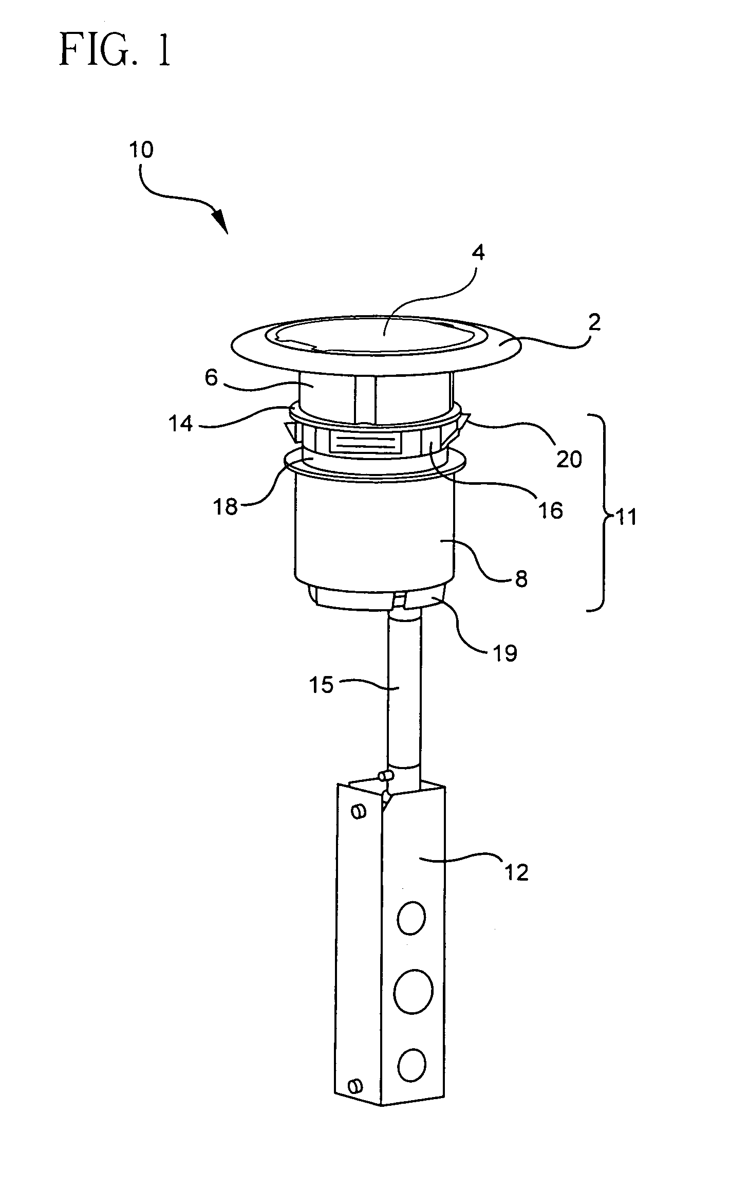
[0035]Initially, FIG. 1 shows the assembled flush poke-through fitting formed in accordance with the present invention, designated generally as 10, with the cover 4 closed on the carpet flange 2. The flush poke-through fitting 10 formed in accordance with the present invention may be sized to fit within a two- to four-inch diameter hole. In a preferred...


PUM


Abstract

A flush poke-through fitting, with both electrical power and data communication access, includes a data jack face plate that can be replaced without disassembly of any other part of the fitting. The data jack face plate is also removable without disruption of power to the electrical outlets. Increased wiring space for flexibility in electrical outlet orientation and improved conductor organization during assembly is also provided by pins that support the electrical contacts in the electrical receptacle when assembled.

Description

BACKGROUND OF THE INVENTION[0001]The present invention relates generally to flush poke-through fittings, and more particularly, to a flush poke-through fitting that provides easy interchangeability of data jack mounts and flexibility in the orientation of the electrical outlets.[0002]One problem commonly encountered in the maintenance and renovation of a facility, a multi-floor office building for example, is how to safely and efficiently add access to electrical power and data communication lines in areas not provided for in the original architectural and electrical planning. Poke-through fittings have offered one alternative to the use of above-ground conduits in providing such access.[0003]A poke-through fitting is an apparatus developed for use in an interfloor hole, typically of two (2) to four (4) inch diameter, formed by drilling through a concrete floor of a multistory building. Power and communication lines are routed beneath the floor and up through the hole, allowing acce...

Claims


Application Information

Patent Timeline
Patent Type & Authority Patents(United States)
IPC IPC(8): H02G3/04H02G3/18
CPCH02G3/185H02G3/0493
Inventor DRANE, MARK R.MICHAELIS, DANIEL K.
Owner THOMAS & BETTS INT INC
Learn More