
Golf range tee

a golf range and tee technology, applied in the field of golf accessories, can solve the problems of “unacceptable inconvenience, golfers can never find rubber tees of a desired length, and it is difficult for golfers to provide rubber tees of every different lengths

Inactive Publication Date: 2006-05-30
CHANG REA TOWER
View PDF8 Cites 27 Cited by
  • Summary
  • Abstract
  • Description
  • Claims
  • Application Information

AI Technical Summary

Benefits of technology

"The present invention provides a golf range tee that can securely mount a golf tee and adjust the height of the golf ball being teed up while preventing the tee from being broken after the ball is hit. The tee has a holding channel for inserting the golf tee, a sliding slot for the tee to slide along, a holding muscle to secure the tee, and a hitting guider to align the hitting direction of the ball. The tee can be used on the mat of a driving range and is economical and efficient. The invention does not require any expensive or complicated mechanical components."

Problems solved by technology

It seems like whenever a golfer go to a driving range, the golfer can never find a rubber tee having a desired length.
However, it is difficult for them to provide rubber tees of every different length to satisfy every customer.
The ball is teed up either too high or too low, which produces undersirable results.
However, when golfers go to the driving range and cannot find the right rubber tee to tee up the ball correctly, they live with this “bearable” inconvenience.
It is a small problem but one that will nullify the practice the golfer puts in.
The present rubber tees are just not flexible enough to allow a golfer to do this.
Also, there is no practice of the motion or pre-shot routine of actually putting the ball and tee in one's hand and inserting the tee into the ground when practicing with the rubber tee since the golf tee cannot directly be inserted into the mat.
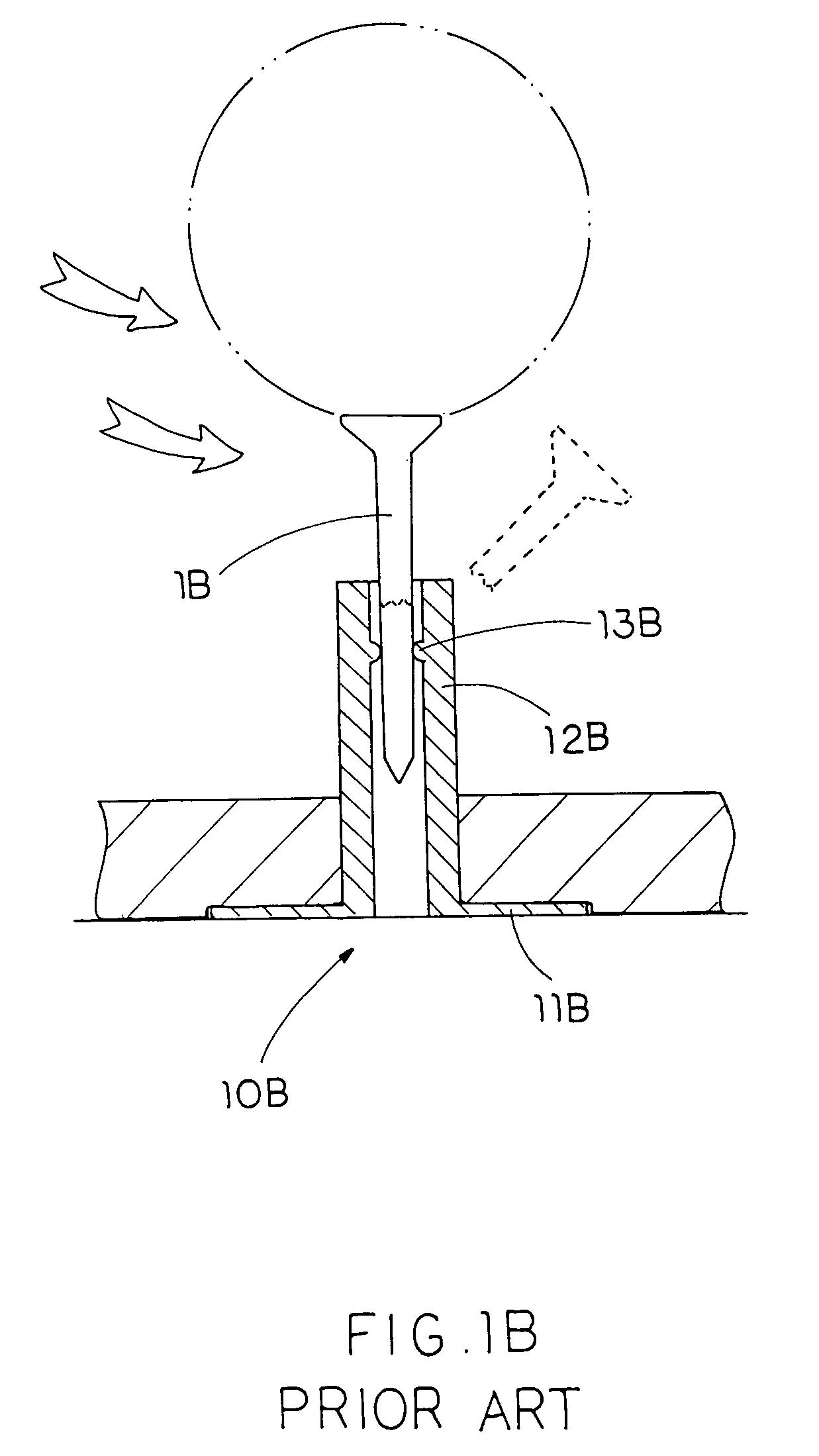
It is very troublesome to take out the golf range tee 10B from the mat in order to remove the broken bottom portion of the wooden golf tee 1B and then replace the golf range tee 10B on the mat again after every or couple golf swings.

Method used


Image

  • Golf range tee
  • Golf range tee
  • Golf range tee

Examples


Embodiment Construction

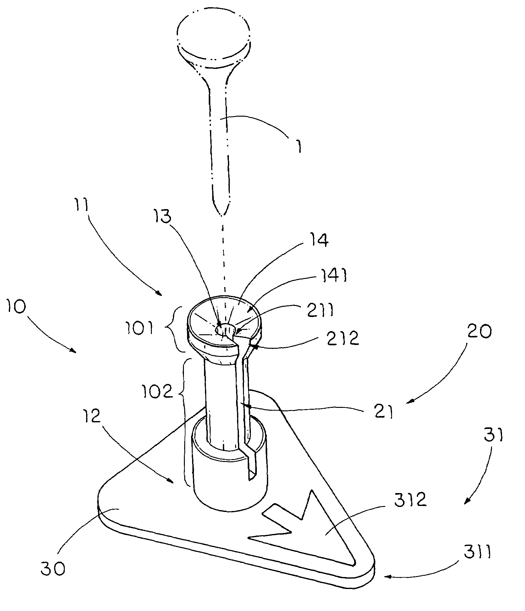
[0029]Referring to FIGS. 2 and 3 of the drawings, a golf range tee for supporting a golf tee 1 according to a preferred embodiment of the present invention is illustrated, wherein the golf range tee comprises a hollow supporting frame 10 and a retention arrangement 20.

[0030]The supporting frame 10 has an upper end 11 and a lower end 12, and defining a holding channel 13 extending from the upper end 11 towards the lower end 12 for a shaft of the golf tee 1 to slidably insert into the holding channel 13 so as to selectively adjust a height a cup of the golf tee 1 with respect to the ground level.

[0031]The retention arrangement 20 has a sliding slot 21 radially formed at the supporting frame 10 from the upper end 11 thereof to communicate the holding channel 13 with an exterior of the supporting frame 10. Therefore, when an impact force is applied at the golf tee 1, the golf tee 1 is forced to slide from the holding channel 13 through the sliding slot21 so as to distribute the impact f...


PUM


Abstract

A golf range tee includes a hollow supporting frame and a retention arrangement. The supporting frame has an upper end and a lower end, and defining a holding channel extending from the upper end towards the lower end for a shaft of the golf tee to slidably insert into the holding channel so as to selectively adjust a height a cup of the golf tee with respect to the ground. The retention arrangement has a sliding slot radially formed at the supporting frame from the upper end thereof to communicate the holding channel with an exterior of the supporting frame. Therefore, when an impact force is applied at the golf tee, the golf tee is forced to slide from the holding channel through the sliding slot so as to distribute the impact force at the golf tee to prevent the golf tee from being broken.

Description

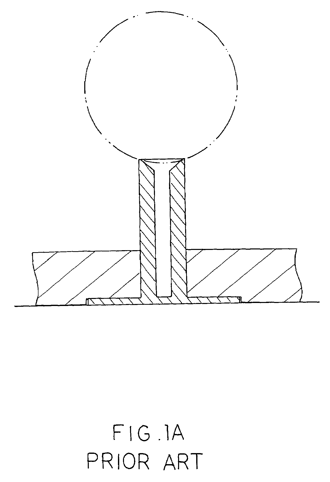
BACKGROUND OF THE PRESENT INVENTION[0001]1. Field of Invention[0002]The present invention relates to a golf accessory, and more particularly to a golf range tee, wherein a golf tee is detachably inserted into the golf range tee to selectively adjust a height of a golf ball being tee-up from the ground while the golf tee is slid to offset to the golf range tee after the impact of the golf ball so as to prevent the golf tee from being broken upon the impact.[0003]2. Description of Related Arts[0004]Golfers practice to improve. Generally, golfers go to driving range for practice. Most driving ranges nowadays use mats instead of growing real grass for the simple reason of keep maintenance cost low. A rubber tee is inserted through an opening in the mat such that when a golfer wants to tee up the ball, he or she is able to place the golf ball on the rubber tee, as shown in FIG. 1A.[0005]Most mats are about 1 inch thick and therefore the rubber tees are at least one and a half inches long...

Claims


Application Information

Patent Timeline
Patent Type & Authority Patents(United States)
IPC IPC(8): A63B57/00
CPCA63B57/0018A63B57/10A63B57/13A63B57/19A63B57/15
Inventor CHANG, REA TOWER
Owner CHANG REA TOWER
Learn More