
Engine starting system

a technology of engine starting and starting system, which is applied in the direction of engine starters, machines/engines, electric control, etc., can solve the problems of unfavorable engine operation, large cost increase, and inability to use a starter motor in an idle stop system. to achieve the effect of quick restarting an engin

Inactive Publication Date: 2006-05-30
MAZDA MOTOR CORP
View PDF2 Cites 47 Cited by
  • Summary
  • Abstract
  • Description
  • Claims
  • Application Information

AI Technical Summary

Benefits of technology

Enables quick and reliable engine restarts by providing sufficient starting torque without the need for a starter motor, reducing delays and extending the durability and cost-effectiveness of the system.

Problems solved by technology

Using this conventional approach employing a starter motor in an idle stop system is impractical, however.
Therefore, the starter motor, if employed in an idle stop system, must have considerably high durability, which results in an unwanted cost increase.
Immediately before complete engine stop when engine speed is extremely low, however, rotational inertial force of the engine is extremely small.
Even when ordinary start-up control operation is performed as described above under such conditions, an adequate starting torque may not be obtained, resulting in a failure to restart the engine.
It is recognized from the foregoing discussion that the conventional engine control systems have a problem that these engine control systems must wait for the engine to completely stop before restarting the engine if an engine restart request is given in the engine stopping period by the driver or else, and this causes some delay in restarting the engine from the point of the engine restart request.

Method used


Image

  • Engine starting system
  • Engine starting system
  • Engine starting system

Examples


Embodiment Construction

[0038]A preferred embodiment of the invention is now described in detail with reference to the accompanying drawings.

General Structure of Engine Control System

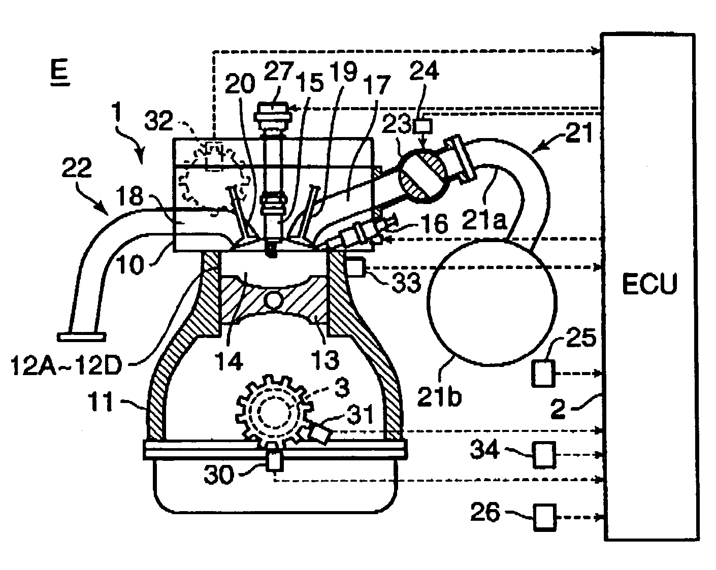
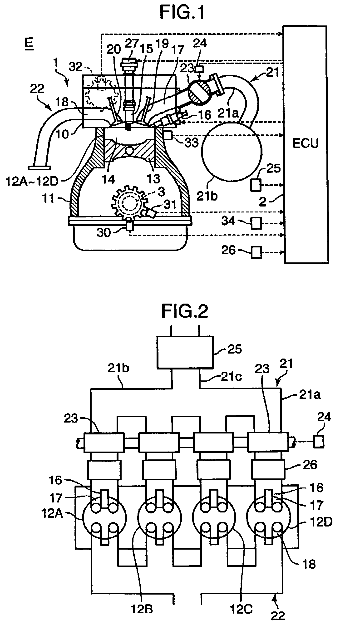
[0039]FIGS. 1 and 2 are diagrams schematically showing the structure of an engine system E provided with an engine starting system according to the embodiment of the invention. Referring to FIG. 1, the engine system E includes an engine 1 having a cylinder head 10 and a cylinder block 11 and an electronic control unit (ECU) 2. The engine 1 has four cylinders 12A–12D as shown in FIG. 2. Pistons 13 connected to a crankshaft 3 are fitted in the individual cylinders 12A–12D whereby a combustion chamber 14 is formed above the piston 13 in each of the cylinders 12A–12D as shown in FIG. 1.

[0040]Generally, a four-cycle multicylinder engine is constructed in such a fashion that individual cylinders undergo successive combustion cycles of intake, compression, expansion and exhaust strokes with a specific phase delay from one cylinder to...


PUM


Abstract

When an engine restart request is given in an engine stopping period which begins at a point of fuel supply interruption and ends at a point of complete engine stop, an engine starting system judges whether TDC engine speed detected immediately before is equal to or lower than a specific value “A”, the counted number of reverse running motions of the engine is 0, and a piston in an expansion stroke cylinder is relatively close to TDC. If the judgment result is in the affirmative with all these conditions satisfied, the engine starting system injects fuel into the expansion stroke cylinder and then ignites and combusts a mixture produced therein. The engine starting system also injects the fuel into a compression stroke cylinder and then ignites and combusts a mixture produced therein when a piston in the compression stroke cylinder has gone beyond TDC.

Description

BACKGROUND OF THE INVENTION[0001]1. Field of the Invention[0002]The present invention relates generally to an engine starting system for restarting an engine which has once stopped automatically under engine idle conditions in response to an engine restart request, and in particular to a start control technique used for restarting an engine when an engine restart request is given in an engine stopping period which begins at a point of fuel supply interruption and ends at a point of complete engine stop.[0003]2. Description of the Related Art[0004]There exist conventionally known engine control systems devised for reducing fuel consumption and carbon dioxide (CO2) emissions, for instance. One example of such engine control systems is an idle stop system which causes an engine to automatically stop during engine idle operation and automatically restart when an engine restart request, such as a driver's operation for starting, occurs.[0005]A generally known method of restarting a once ...

Claims


Application Information

Patent Timeline
Patent Type & Authority Patents(United States)
IPC IPC(8): F02N17/00F02D41/04F02D41/06F02D41/12F02N11/08F02N99/00
CPCF02D41/042F02D41/065F02D41/123F02N11/0814F02N11/0844F02N99/006F02N19/005Y02T10/48F02N2019/007F02N2200/021F02N2200/022Y02T10/40
Inventor TETSUNO, MASAYUKITAGA, JUNICHISUGIYAMA, TAKANORIHOSOYA, HIDEKINAKAYAMA, YOSHITERUARAKI, KEIJI
Owner MAZDA MOTOR CORP
Learn More