
Method and system for controlling an electronic device

a technology of electronic devices and control systems, applied in the direction of burglar alarm mechanical actuation, instruments, navigation instruments, etc., can solve problems such as unwanted electromagnetic interference, and achieve the effect of reducing power consumption and easy concealmen

Inactive Publication Date: 2006-05-23
TRIMBLE NAVIGATION LTD
View PDF13 Cites 115 Cited by
  • Summary
  • Abstract
  • Description
  • Claims
  • Application Information

AI Technical Summary

Benefits of technology

[0008]Accordingly, a need exists for a low-cost portable position determining and / or reporting device which is small enough to be easily concealed upon an asset which is being tracked. While meeting the above need, a further need exists for a method for reducing the power consumption of the above stated device. Additionally, while meeting the above stated needs, it would be advantageous to provide a device which can trigger another electrical device to perform a particular task upon entering or leaving a designated location zone.
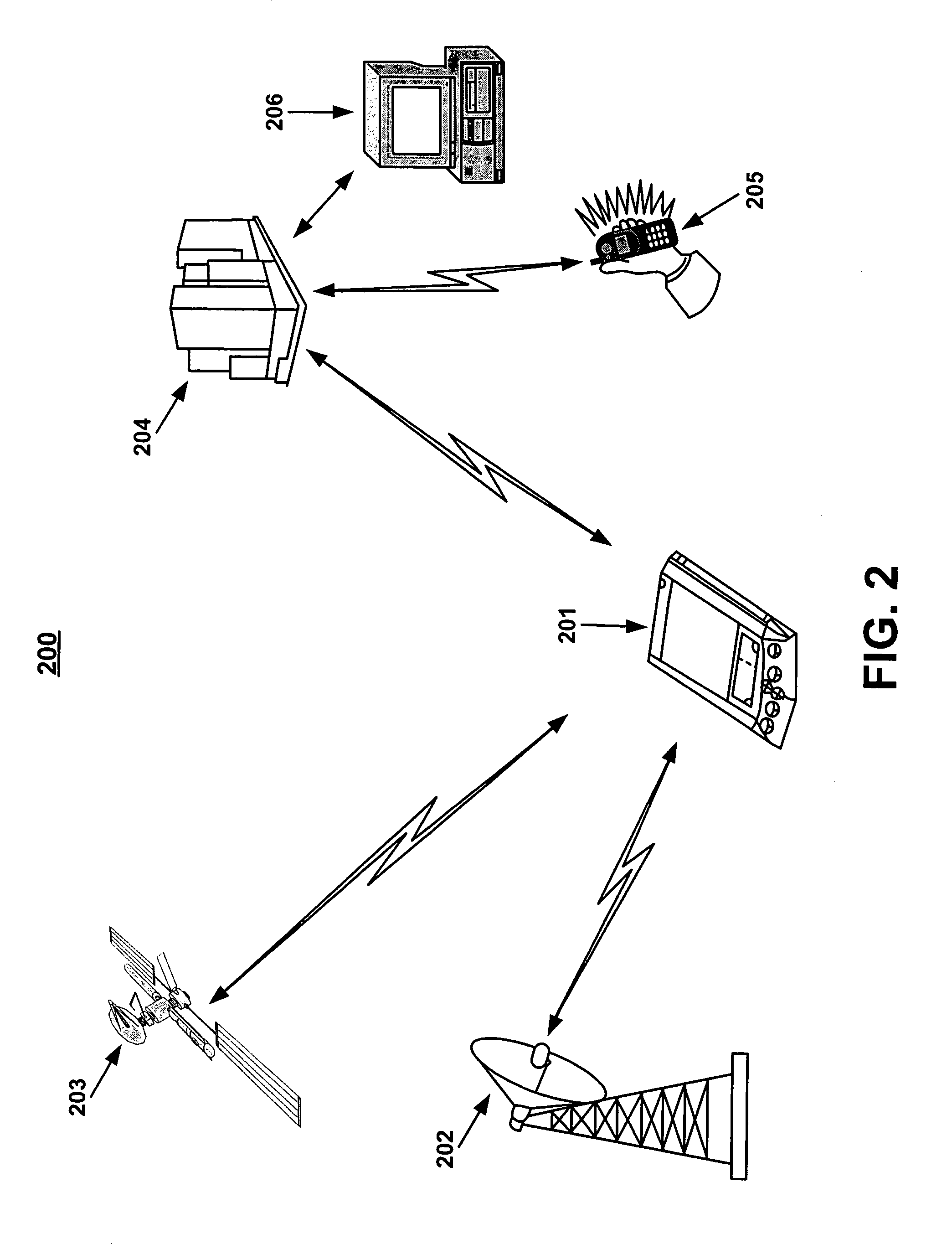
[0010]Embodiments of the present invention can be used to cause an electronic device to perform a particular task upon entering or leaving a designated zone. For example, the present invention can be used to automatically inactivate the electronic device (e.g., a cellular telephone) when it is brought into a restricted area. This may include theaters, airports, hospitals, gas stations, or other areas where operating the electronic device may cause, for example, unwanted electromagnetic interference with other equipment in the area. A user can designate these areas to reduce the possibility of the user forgetting to shut down the device. In another embodiment, the user can accept a pre-packaged list of such exclusion zones for automatic implementation of this shut-off feature.

Problems solved by technology

This may include theaters, airports, hospitals, gas stations, or other areas where operating the electronic device may cause, for example, unwanted electromagnetic interference with other equipment in the area.

Method used


Image

  • Method and system for controlling an electronic device
  • Method and system for controlling an electronic device
  • Method and system for controlling an electronic device

Examples


Embodiment Construction

[0019]Reference will now be made in detail to embodiments of the present invention, examples of which are illustrated in the accompanying drawings. While the present invention will be described in conjunction with the following embodiments, it will be understood that they are not intended to limit the present invention to these embodiments alone. On the contrary, the present invention is intended to cover alternatives, modifications, and equivalents which may be included within the spirit and scope of the present invention as defined by the appended claims. Furthermore, in the following detailed description of the present invention, numerous specific details are set forth in order to provide a thorough understanding of the present invention. However, embodiments of the present invention may be practiced without these specific details. In other instances, well-known methods, procedures, components, and circuits have not been described in detail so as not to unnecessarily obscure aspe...


PUM


Abstract

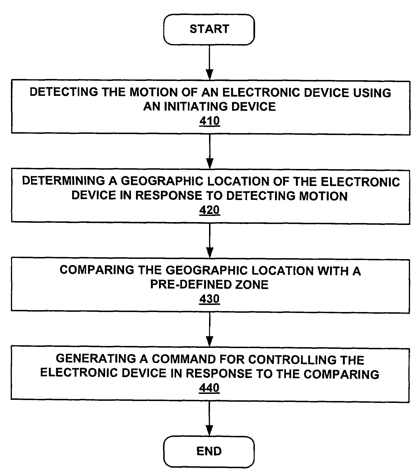
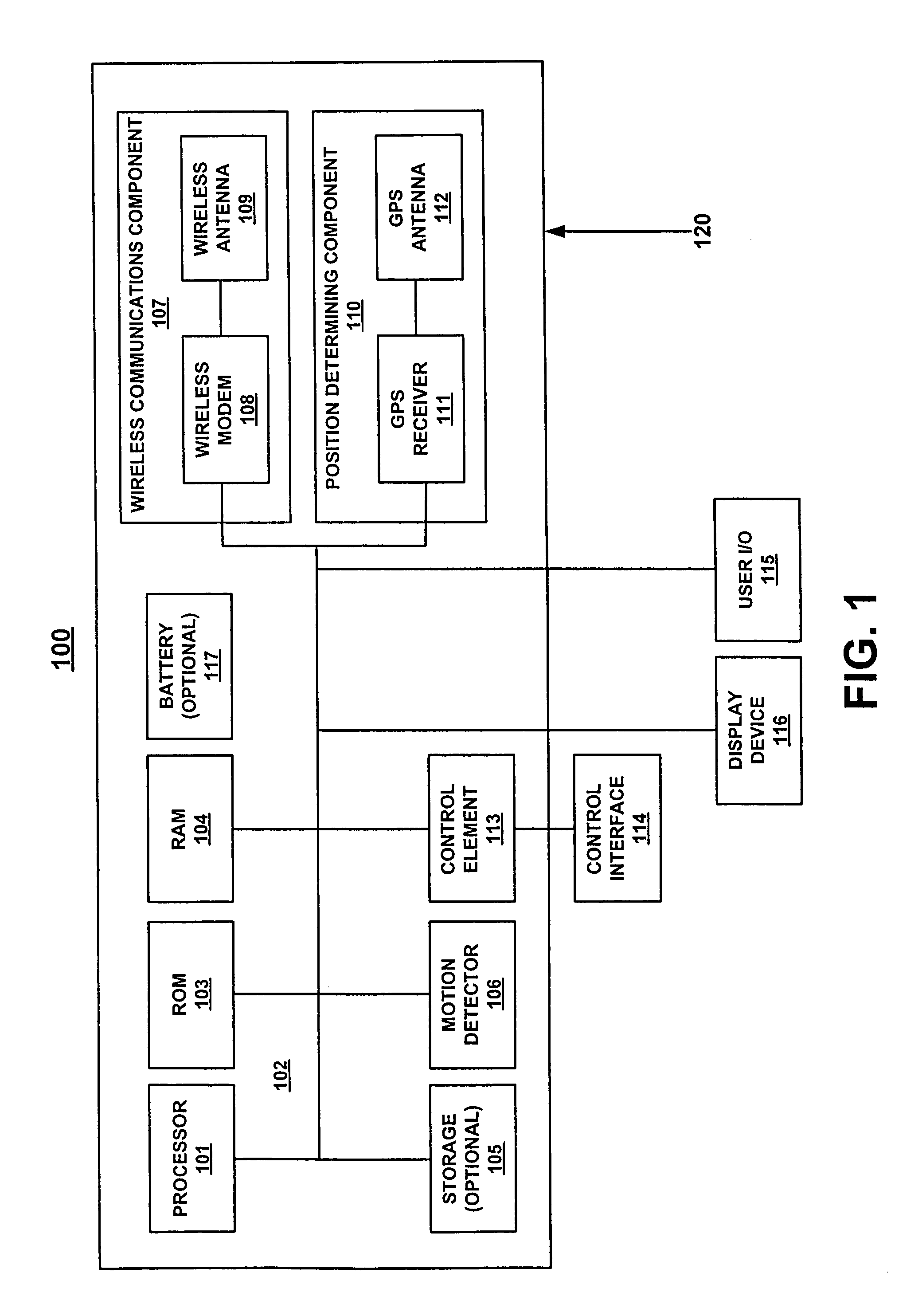
The present invention is a method and system for controlling an electronic device. In one embodiment, a controller is coupled with a position determining component, and a motion detecting component. In one embodiment, the motion detecting component detects motion of the electronic device and generates a signal to the controller indicating the motion. The controller, in response to the signal, causes the position determining component to determine the geographic location of the electronic device. The geographic location is compared with a pre-defined zone and, in response to the comparing, a command is generated for controlling the electronic device.

Description

RELATED APPLICATIONS[0001]This is a continuation-in-part of application Ser. No. 10 / 222,532 filed Aug. 15, 2002 now U.S. Pat. No. 6,401,853 titled A Portable Motion-Activated Position Reporting Device by Dennis Workman, assigned to the assignee of the present invention, and which is hereby incorporated by reference in its entirety herein.FIELD OF THE INVENTION[0002]Embodiments of the present invention are related to a device for determining and reporting the position of a person or object, and for providing control information.BACKGROUND OF THE INVENTION[0003]Position reporting devices are frequently used to locate and report the position of a person or object. A typical position reporting device combines a navigation system such as the Global Positioning System (GPS) module with a mobile communications system such as a cellular modem to determine the position or geographic location of a person or asset being tracked and report their position to a tracking facility. Position reporti...

Claims


Application Information

Patent Timeline
Patent Type & Authority Patents(United States)
IPC IPC(8): G01C21/26G01S5/00G01S19/48G08B13/14G08B25/10
CPCG01S5/0018G08B25/10G08B21/0269G08B13/1436
Inventor JANKY, GREGORY T.WORKMAN, DENNISBERGSTROM, AMI
Owner TRIMBLE NAVIGATION LTD
Learn More